


11-49
ATM Switch Router Software Configuration Guide
OL-7396-01
Chapter 11 Configuring ATM Routing and PNNI
Advanced PNNI Configuration
Example
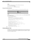
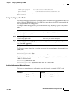
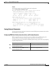
The following example shows the PNNI complex node configuration:
Switch# show atm pnni aggregation node
PNNI nodal aggregation for local-node 2 (level=56, child PG level=60)
Complex node representation, exception threshold: 60%
Configured nodal aggregation modes (per service class):
CBR VBR-RT VBR-NRT ABR UBR
~~~~~~~~~~~ ~~~~~~~~~~~ ~~~~~~~~~~~ ~~~~~~~~~~~ ~~~~~~~~~~~
best-link best-link best-link best-link aggressive
Summary Complex Node Port List:
Port ID Rem Inn Agg-Token Border Cnt In-Spoke Out-Spoke Agg-Accur
~~~~~~~~ ~~~~~~~ ~~~~~~~~~~ ~~~~~~~~~~ ~~~~~~~~~ ~~~~~~~~~ ~~~~~~~~~~
21FB000 12 0 1 default default ok
2371000 13 0 1 default default ok
Summary Complex Node Bypass Pairs List (exception bypass pairs only)
/~~~~~~~~ LOWER PORT ID ~~~~~~~~\ /~~~~~~~~ HIGHER PORT ID ~~~~~~~\
Port ID Rem Inn Agg-Token Inacc Port ID Rem Inn Agg-Token Inacc Exceptns
~~~~~~~~ ~~~~~~~ ~~~~~~~~~~ ~~~~~ ~~~~~~~~ ~~~~~~~ ~~~~~~~~~~ ~~~~~ ~~~~~~~~
21FB000 12 0 no 2371000 13 0 no fwd rev
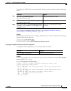
Tuning Protocol Parameters
The tasks in the following subsections describe how to tune the PNNI protocol parameters that can affect
the performance of your network.
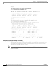
Configuring PNNI Hello, Database Synchronization, and Flooding Parameters
PNNI uses the Hello protocol to determine the status of neighbor nodes and PNNI topology state
elements (PTSEs) to disseminate topology database information in the ATM network.
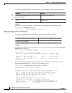
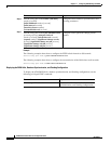
To configure the Hello protocol parameters and PTSE significant change, perform these steps, beginning
in global configuration mode:
Command Purpose
Step 1
Switch(config)# atm router pnni
Switch(config-atm-router)#
Enters ATM router PNNI mode.
Step 2
Switch(config-atm-router)# node node-index
Switch(config-pnni-node)#
Enters node configuration mode.