


21-3
ATM Switch Router Software Configuration Guide
OL-7396-01
Chapter 21 Configuring IMA Port Adapter Interfaces
Configuring the T1/E1 IMA Port Adapter
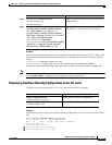
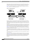
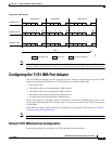
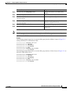
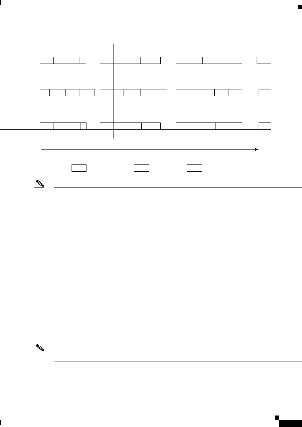
Figure 21-2 IMA Frames
Note These ICP cells are distributed more evenly over the IMA frame but are shown closer for illustration
purposes. Within an IMA frame, the ICP cells on all links have the same IMA frame sequence number.
Configuring the T1/E1 IMA Port Adapter
The T1/E1 IMA port adapter provides eight physical ports. Each port adapter supports up to four IMA
groups and independent ATM interfaces. The following are possible combinations:
• Four IMA groups
• Three IMA groups and one independent ATM interface
• Two IMA groups and two independent ATM interfaces
• One IMA group and three independent ATM interfaces
• No IMA group and four independent ATM interfaces
The T1 line operates at 1.544 Mbps, which is equivalent to 24 time slots (DS0 channels). The T1 time
slot provides usable bandwidth of n x 64 kbps, where n is the time slot from 1 to 24. The E1 line operates
at 2.048 Mbps.
T1/E1 IMA port adapters support interface overbooking. For configuration information, see Chapter 9,
“Configuring Resource Management.”
Note By default, T1/E1 IMA interfaces are shut down when the port adapter is installed.
Default T1/E1 IMA Interface Configuration
The following defaults are assigned to all T1/E1 IMA port adapter interfaces:
ICP0 F ATM F ATM
...
IMA frame 0
ICP1 F ATM F F
...
IMA frame 1
ICP2 F ATM ATM ATM
...
IMA frame 2
F F ATM ICP0 ATM
...
F ATM ATM ICP1 ATM
...
F F ATM ICP2 F
...
ATM ICP0 ATM F ATM
...
ATM ICP1 ATM F ATM
...
ATM ICP2 ATM ATM F
...
Time
0 1 2 3 M-1 0 1 2 3 M-1 0 1 2 3 M-1
ATM ATM layer cell
Interface 0/0/1
Interface 0/0/2
Interface 0/0/3
F Filler cell ICP# ICP cell in frame #
24338