


11-24
ATM Switch Router Software Configuration Guide
OL-7396-01
Chapter 11 Configuring ATM Routing and PNNI
Basic PNNI Configuration
Example
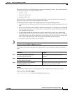
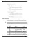
The following example shows the ATM PNNI summary address configuration using the show atm pnni
summary privileged EXEC command:
Switch# show atm pnni summary
Codes: Node - Node index advertising this summary
Type - Summary type (INT - internal, EXT - exterior)
Sup - Suppressed flag (Y - Yes, N - No)
Auto - Auto Summary flag (Y - Yes, N - No)
Adv - Advertised flag (Y - Yes, N - No)
Node Type Sup Auto Adv Summary Prefix
~~~~ ~~~~ ~~~ ~~~~ ~~~ ~~~~~~~~~~~~~~~~~~~~~~~~~~~~~~~~~~~~~~~~~~~~~~~~~~~
1 Int N Y Y 47.0091.8100.0000.0040.0b0a.2a81/104
2 Int N Y N 47.01b1.0000.0000.0000.00/80
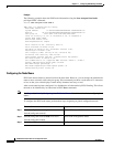
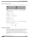
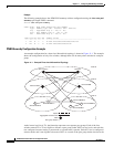
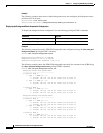
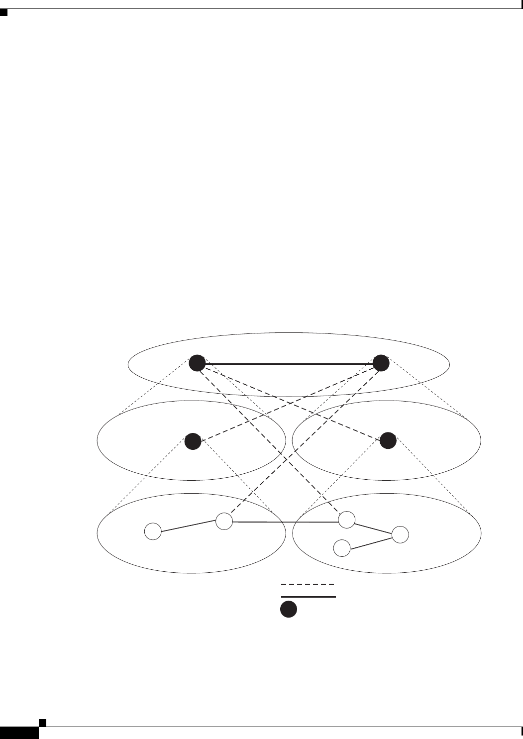
PNNI Hierarchy Configuration Example
An example configuration for a three-level hierarchical topology is shown in Figure 11-1. The example
shows the configuration of only five switches, although there can be many other switches in each peer
group.
Figure 11-1 Example Three-Level Hierarchical Topology
At the lowest level (level 72), the hierarchy represents two separate peer groups. Each of the four
switches named T2 to T5 are eligible to become a peer group leader (PGL) at two levels, and each has
two configured ancestor nodes (a parent node or a parent node’s parent). Switch T1 has no configured
ancestor nodes and is not eligible to become a PGL. As a result of the peer group leader election at the
T5
SanFran.BldA.T5
SanFran.BldA.T4
Uplinks
Aggregated horizontal links
LGNs
Peer group leaders
T4
10132
SanFran.BldA
*
*
*
*
T3
NewYork.BldB.T1
NewYork.BldB.T2
NewYork.BldB.T3
T2
T1
NewYork.BldB
Level 64
Level 56
Level 72
*
NewYork
San Francisco