


16-11
ATM Switch Router Software Configuration Guide
OL-7396-01
Chapter 16 Configuring Tag Switching and MPLS
Configuring Tag Switching
To connect the source and destination switch VP tunnels, proceed to the next section, “Connecting the
VP Tunnels.”
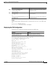
Displaying the VP Tunnel Configuration
To display the VP tunnel configuration, use the following EXEC command:
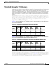
The following example shows PVP 51 configured on ATM interface 0/1/1:
Switch# show atm vp
Interface VPI Type X-Interface X-VPI Status
ATM0/1/1 51 PVP TUNNEL
Connecting the VP Tunnels
To complete the VP tunnel, you must configure the ATM ports on the intermediate switch to designate
where to send packets coming from the source switch and going to the destination switch.
To connect the permanent virtual path (PVP), perform the following steps, beginning in interface
configuration mode:
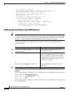
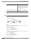
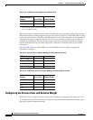
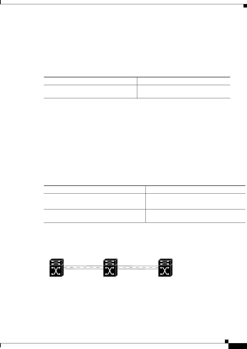
Figure 16-3 shows an example configuration on an intermediate switch.
Figure 16-3 Connecting the VP Tunnels
Example
In the following example, PVP 51 on ATM interface 0/1/1 is connected to PVP 101 on ATM
interface 0/1/3:
Switch(config)# interface atm 0/1/1
Switch(config-if)# atm pvp 51 interface atm 0/1/3 101
Switch(config-if)# exit
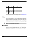
Command Purpose
show atm vp Displays the VP tunnel configuration on an
interface.
Command Purpose
Step 1
Switch(config)# interface atm card/subcard/port
Switch(config-if)#
Enters interface configuration mode on the
specified ATM interface.
Step 2
Switch(config-if)# atm pvp vpi interface atm
card/subcard/port vpi-B
Connects the PVP from the source switch to the
destination switch.
0/1/1
PVP 51 PVP 101
0/1/3
Source switch Intermediate switch Destination switch
S6808