


25-43
ATM Switch Router Software Configuration Guide
OL-7396-01
Chapter 25 Configuring ATM Router Module Interfaces
Configuring VC Bundling with IP and ATM QoS
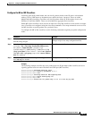
Displaying the Policy Map Configuration
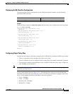
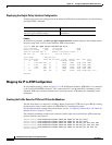
To display the policy map configuration, use the following privileged EXEC command:
Example
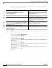
In the following example, the show policy-map command displays the configuration of the policy-map
arm2-switch1:
Switch1# show policy-map arm2-switch1
Policy Map arm2-switch1
class voice
bandwidth 200000
random-detect buffer-group 3 max-probability 100 freeze-time 15
class video
bandwidth 175000
random-detect buffer-group 2 max-probability 100 freeze-time 15
class HiPri
bandwidth 100000
random-detect buffer-group 1 max-probability 100 freeze-time 15
class class-default
bandwidth 25000
random-detect buffer-group 0 max-probability 100 freeze-time 15
Switch1#
Applying the Output Policy Map on the Enhanced ATM Router Module
This section describes applying the policy map to the output enhanced ATM router module.
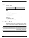
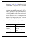
To apply the output service policy on the enhanced ATM router module subinterface, use the following
commands, beginning in global configuration mode:
Example
The following example applies a service policy to the Gigabit Ethernet interface:
Switch1(config)# interface atm 9/0/0
Switch1(config-if)# service-policy output arm2-switch1
Switch1(config-if)# end
Switch1#
Command Purpose
show policy-map [policy-map-name] Displays the policy map information.
Command Purpose
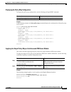
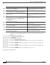
Step 1
Switch(config)# interface atm
card/subcard/port[.subinterface#]
Switch(config-if)#
Specifies the Gigabit Ethernet interface or
ATM subinterface and enters interface
configuration mode.
Step 2
Switch(config-if)# service-policy {input | output}
policy-map-name
Attaches the policy map you specify to the
interface.