


7-56
ATM Switch Router Software Configuration Guide
OL-7396-01
Chapter 7 Configuring Virtual Connections
Configuring Backup Addresses for Soft PVC and Soft PVP Connections
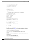
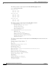
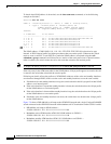
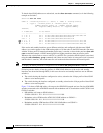
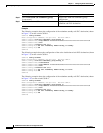
To check what NSAP address is advertised, use the show atm route command, as in the following
example on Switch-C.
Switch-C# show atm route
Codes: P - installing Protocol (S - Static, P - PNNI, R - Routing control),
T - Type (I - Internal prefix, E - Exterior prefix, SE -
Summary Exterior prefix, SI - Summary Internal prefix,
ZE - Suppress Summary Exterior, ZI - Suppress Summary
Internal)
P T Node/Port St Lev Prefix
~ ~~ ~~~~~~~~~~~~~~~~ ~~ ~~~ ~~~~~~~~~~~~~~~~~~~~~~~~~~~~~~~~~~~~~~~~~~~~~~~~~~~
P I 12 0 UP 0 47.0079.0000.0000.0000.0000.0000.00a0.3e00.0001/152
P I 12 0 UP 0 47.0091.8100.0000.0060.3e5a.4500/104
P I 10 0 UP 0 47.0091.8100.0000.0060.3e5a.4501/104
P I 9 0 UP 0 47.0091.8100.0000.0090.2156.1401/104
P SI 1 0 UP 0 47.0091.8100.0000.0090.215d.b801/104
P I 9 0 UP 0 47.0091.8100.1111.1111.1111.2222.2222.2222.2222/152
The NSAP address, 47.0091.8100.1111.1111.1111.2222.2222.2222.2222.00 is advertised as type
internal. A PNNI internal prefix has higher precedence than an exterior prefix. Whenever the switch
needs to route a soft PVC or soft PVP for a particular NSAP address (associated using the soft
redundancy group command) and if there are two entries of the same prefix (one is internal and the
other is exterior), the switch routes the call to the node that advertises the internal prefix.
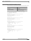
Note To display the PNNI precedence configuration use the show atm pnni precedence command.
If the only entry in the ATM route table for the NSAP address 19-byte prefix appears as exterior the call
is routed to the switch that advertised the exterior prefix.
Following are details of how the prefixes of ATM NSAP addresses of the active and standby interfaces
are advertised through PNNI (in this case the active and standby interfaces are on the same switch):
1. If both the active and standby interfaces are up, the switch advertises the 19-byte prefix of that NSAP
address as an internal prefix.
2. If the active interface is up and the standby interface is down, the switch advertises the 19-byte prefix
of that NSAP address as an internal prefix.
3. If the active interface is down and the standby interface is up, the switch advertises the 19-byte prefix
of that NSAP address as an exterior prefix.
4. If both the active and standby interfaces are down, the switch does not advertise the 19-byte prefix
of that NSAP address.
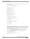
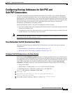
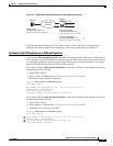
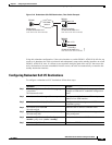
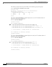
Figure 7-9 shows a DSLAM with a call setup to the ATM PNNI network and a single Catalyst 8540 MSR
switch connected to the ATM PNNI network with redundant soft VC destinations on the C8540-1 switch:
• DSLAM has call setup to NSAP address—
47.0091.8100.1111.1111.1111.1111.1111.1111.1111.00
• Redundant active ATM interface ATM 1/1/0 NSAP address on C8540-1—
47.0091.8100.1111.1111.1111.1111.1111.1111.1111.00
• Redundant standby ATM interface ATM 1/1/1 NSAP address on C8540-1—
47.0091.8100.1111.1111.1111.1111.1111.1111.1111.00