


21-7
ATM Switch Router Software Configuration Guide
OL-7396-01
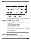
Chapter 21 Configuring IMA Port Adapter Interfaces
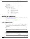
Configuring IMA Group Functions
Note The IMA group numbers on each end of the interface can differ. For example, you can configure the
interfaces in IMA group 1 on Switch A and in IMA group 2 on Switch B.
Example
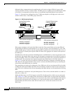
The following example shows how to create the IMA group interface 0/0/ima1 shown in Figure 21-1
starting with Switch A, ATM interface 0/0/1:
SwitchA(config)# interface atm 0/0/1
SwitchA(config-if)# shutdown
SwitchA(config-if)# ima-group 1
SwitchA(config-if)# no shutdown
SwitchA(config-if)# exit
SwitchA(config)# interface atm 0/0/ima1
SwitchA(config-if)# no shutdown
The following example shows how to create the IMA group interface 4/1/ima1 shown in Figure 21-1 on
Switch B, ATM interface 4/1/4:
SwitchB(config)# interface atm 4/1/4
SwitchB(config-if)# shutdown
SwitchB(config-if)# ima-group 1
SwitchB(config-if)# no shutdown
SwitchB(config-if)# exit
SwitchB(config)# interface atm 4/1/ima1
SwitchB(config-if)# no shutdown
Step 3
Switch(config-if)# ima-group number Assigns the interface to an IMA group
number.
Step 4
Switch(config-if)# no shutdown Reenables the interface.
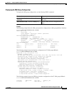
Step 5
Switch(config-if)# exit
Switch(config)#
Returns to global configuration mode.
Step 6
Switch(config)# interface atm card/subcard/imagroup
Switch(config-if)#
Specifies the IMA group 0 to 3 and enters
interface configuration mode.
Step 7
Switch(config-if)# no shutdown Creates the IMA group.
Step 8
— Repeat this procedure on the other end of the
connection.
Command Purpose