


11-62
ATM Switch Router Software Configuration Guide
OL-7396-01
Chapter 11 Configuring ATM Routing and PNNI
PNNI Connection Trace
Examples
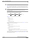
The following example shows an active PNNI connection trace summary for the connections shown in
Figure 11-4:
Switch_10# show atm pnni trace connection 20
Connection Trace Request-index: 20
Connection Type: ATM-VC
Source Interface: ATM1/0/2 Direction: Incoming
VPI: 0 Call-Reference: Not specified
VCI: 136 Endpoint-Reference: 0x6
Time to age: 490 seconds
Trace Flags: Connection-Id, Call-Reference
Pass Along: Requested
Trace Result: Trace Completed Normally
Node Outgoing-port
~~~~ ~~~~~~~~~~~~~
Switch_10 ATM1/0/1
Switch_09 ATM1/0/3
Switch_08 ATM1/0/0
Switch_06 ATM3/0/1
Switch_03 ATM1/1/0
Switch_05 0x0
Switch_10#
Note The Trace Result field indicates whether the trace completed normally or not.
Note The switch names listed under the Node heading indicate the nodes the connection trace traversed.
Note The Outgoing-port heading indicates the outgoing port of each node.
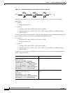
The following example displays the nodes and outgoing ports in hexadecimal mode for the specified
index number variable for the connections shown in Figure 11-4:
Switch_10# show atm pnni trace connection 20 hex-only
Connection Trace Request-index: 20
Connection Type: ATM-VC
Source Interface: ATM1/0/2 Direction: Incoming
VPI: 0 Call-Reference: Not specified
VCI: 136 Endpoint-Reference: 0x6
Time to age: 490 seconds
Trace Flags: Connection-Id, Call-Reference
Pass Along: Requested
Trace Result: Trace Completed Normally
Node Outgoing-port
~~~~ ~~~~~~~~~~~~~
56:160:47.0091810000000050E2097801.0060705BC701.00 0x80801000
56:160:47.0091810000000004DDECD401.0004DDECD401.00 0x80803000
56:160:47.00918100000000D0BA34E001.00D0BA34E001.00 0x80800000
56:160:47.0091810000000004DDECD301.0004DDECD301.00 0x81801000
56:160:47.00918100000000036B5A4901.00036B5A4901.00 0x80900000
56:160:47.009181000000001007461301.001007461301.00 0x0
Switch_10#