


18-15
ATM Switch Router Software Configuration Guide
OL-7396-01
Chapter 18 Configuring Interfaces
Configuring T1/E1 Trunk Interfaces
Configuring T1/E1 Trunk Interfaces
The T1 and E1 trunk port adapters, used for intercampus or wide-area links, have four ports.
T1/E1 Trunk Interface Configuration
The ATM switch router supports any combination of port adapters. You can configure your switch router
with only the number and type of interfaces required, with up to 64 T1 or E1 interface ports on the
Catalyst 8540 MSR and up to 32 T1 or E1 interface ports on the Catalyst 8510 MSR and
LightStream 1010 ATM switch routers.
The port adapter supports SC-type and BNC connectors while receive and transmit LEDs on each port
give quick, visual indications of port status and operation.
Traffic-pacing allows the aggregate output traffic rate on any port to be set to a rate below the line rates.
This feature is useful when communicating with a slow receiver or when connected to public networks
with peak-rate tariffs.
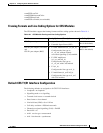
Default T1 and E1 ATM Interface Configuration without Autoconfiguration
If ILMI is disabled or if the connecting end node does not support ILMI, the following defaults are
assigned to all T1 and E1 interfaces:
• ATM interface type = UNI
• UNI version = 3.0
• Maximum VPI bits = 8
• Maximum VCI bits = 14
• ATM interface side = network
• ATM UNI type = private
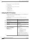
The following port adapter types have specific defaults assigned.
T1 port adapter:
• Framing = ESF
• Line coding = B8ZS
• Cell payload scrambling = off
• Clock source = network-derived
• LBO = 0 to 110 feet
• Auto-ferf on loss of signal (LOS) = on
• Auto-ferf on out of frame (OOF) = on
• Auto-ferf on red = on
• Auto-ferf on loss of cell delineation (LCD) = on
• Auto-ferf on alarm indication signal (AIS) = on