


20-26
ATM Switch Router Software Configuration Guide
OL-7396-01
Chapter20 Configuring Frame Relay to ATM Interworking Port Adapter Interfaces
Configuring Frame Relay to ATM Virtual Connections
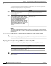
Note The row index for rx-cttr and tx-cttr must be configured before using this optional parameter. See
Chapter 9, “Configuring Resource Management.”
Note When configuring PVC connections, configure the lowest virtual path identifier (VPI) and virtual
channel identifier (VCI) numbers first.
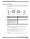
Examples
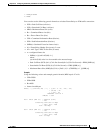
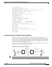
The following example shows how to configure the internal cross-connect Frame Relay to ATM network
interworking PVC on Switch B between serial interface 0/1/0:5, DLCI = 43 and ATM interface 3/0/2,
VPI = 2, VCI = 100 (see Figure 20-3):
Switch-B(config)# interface serial 0/1/0:5
Switch-B(config-if)# frame-relay pvc 43 network interface atm 3/0/2 2 100
The following example shows how to configure the internal cross-connect PVC on Switch C between
serial interface 0/0/1:9, DLCI = 255 and ATM interface 4/1/0, VPI = 2, VCI = 100:
Switch-C(config)# interface serial 0/0/1:9
Switch-C(config-if)# frame-relay pvc 255 network interface atm 4/1/0 2 100
Note The Frame Relay to ATM network interworking PVC must be configured from the serial interface and
cross-connected to the ATM interface.
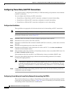
Displaying Frame Relay to ATM Network Interworking PVCs
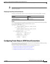
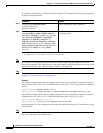
To display the network interworking configuration, use the following EXEC command:
Example
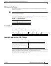
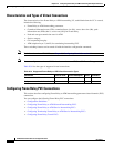
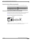
The following example displays the Switch B PVC configuration for serial interface 0/1/0:5:
Switch-B# show vc interface serial 0/1/0:5
Interface Conn-Id Type X-Interface X-Conn-Id Encap Status
Serial0/1/0:5 43 PVC ATM3/0/2 2/100 UP
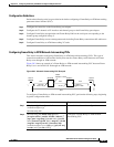
The following example displays the configuration of the Switch B PVC on serial interface 0/1/0:5,
DLCI = 43:
Switch-B# show vc interface serial 0/1/0:5 43
Interface: Serial0/1/0:5, Type: FRPAM-SERIAL
DLCI = 43 Status : ACTIVE
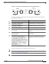
1. The serial interface is created with the channel-group command and configured using the encapsulation frame-relay ietf
command. cgn is the channel group number of a channel group configured using the channel-group command.
2. The dlci value appears in the Conn-Id and X-Conn-Id columns of the show vc command.
3. The overflow queuing option is described in the section, Configuring Overflow Queuing, page 20-43.
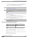
Command Purpose
show vc [interface {atm card/subcard/port
[vpi vci] | serial card/subcard/port:cgn
[dlci]}]
Shows the PVC interface configuration.