


20-2
ATM Switch Router Software Configuration Guide
OL-7396-01
Chapter20 Configuring Frame Relay to ATM Interworking Port Adapter Interfaces
Configuring the Channelized DS3 Frame Relay Port Adapter
Configuring the Channelized DS3 Frame Relay Port Adapter
The channelized DS3 (CDS3) Frame Relay port adapter provides one physical port (45 Mbps). Each DS3
interface consists of 28 T1 lines multiplexed through a single T3 trunk. Each T1 line operates at
1.544 Mbps, which equates to 24 time slots (DS0 channels). A DS0 time slot provides 56 or 64 kbps of
usable bandwidth. You can combine one or more DS0 time slots into a channel group to form a serial
interface. A channel group provides n x 56 or 64 kbps of usable bandwidth, where n is the number of
time slots, from 1 to 24. You can configure a maximum of 127 serial interfaces, or channel groups, per
port adapter.
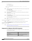
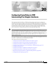
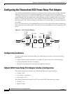
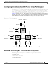
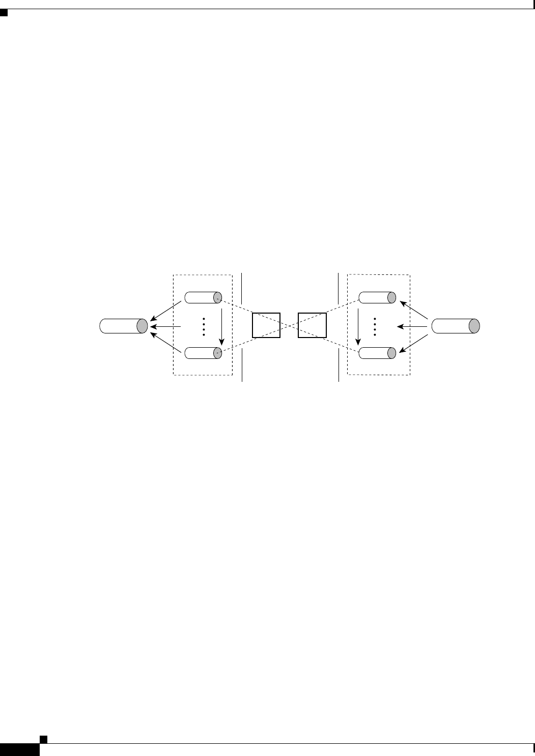
Figure 20-1 illustrates how a T3 trunk demultiplexes into 28 T1 lines that provide single or multiple time
slots mapped across the ATM network. These time slots are then multiplexed to form an outgoing T3 bit
stream.
Figure 20-1 T3/T1 Time Slot Mapping
Configuration Guidelines
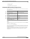
In order to configure the CDS3 Frame Relay port adapter physical interface you need the following
information:
• Digital transmission link information, for example, T3 and T1 clock source and framing type
• Channel information and time slot mapping
• Protocols and encapsulations you plan to use on the new interfaces
Default CDS3 Frame Relay Port Adapter Interface Configuration
The following defaults are assigned to all CDS3 Frame Relay port adapter interfaces:
• Framing—M23
• Clock source—loop-timed
• Cable length—224
The following defaults are assigned to all T1 lines on the CDS3 Frame Relay port adapter:
• Framing— esf
• Speed—64 kbps
T1 line
T1 line
T3 line
TS n x 24
T1 lines
1 to 28
T1 lines
1 to 28
TS n x 24
TS n x 24 TS n x 24
T1 line
T1 line
ATM
switch
ATM
switch
15274
T3 line