


7-20
ATM Switch Router Software Configuration Guide
OL-7396-01
Chapter 7 Configuring Virtual Connections
Configuring Soft PVC Connections
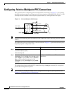
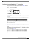
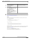
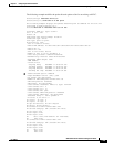
Figure 7-6 illustrates the soft PVC connections used in the following examples.
Figure 7-6 Soft PCV Connection Example
Guidelines for Creating Soft PVCs
Perform the following steps when you configure soft PVCs:
Step 1 Determine which two ports you want to define as participants in the soft PVC.
Step 2 Decide which of these two ports you want to designate as the destination (or passive) side of the
soft PVC.
This decision is arbitrary—it makes no difference which port you define as the destination end of the
circuit.
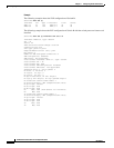
Step 3 Retrieve the ATM address of the destination end of the soft PVC using the show atm address command.
Step 4 Retrieve the VPI/VCI values for the circuit using the show atm vc command.
Step 5 Configure the source (active) end of the soft PVC. At the same time, complete the soft PVC setup using
the information derived from Step 3 and Step 4. Be sure to select an unused VPI/VCI value (one that
does not appear in the show atm vc display).
Note To ensure that the soft PVCs are preserved during a route processor switchover, you must configure the
switch to synchronize dynamic information between the route processors. For more information, see
Chapter 3, “Initially Configuring the ATM Switch Router.”
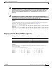
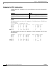
Configuring Soft PVCs
To configure a soft PVC connection, perform the following steps, beginning in privileged EXEC mode:
User A Switch B User DSwitch C
25189
ATM network
IF# = 0/0/2
VPI = 0, VCI = 1000
IF# = 1/1/1
VPI = 0, VCI = 1000
Address = 47.0091.8100.0000.00e0.4fac.b410.4000.0c80.9010.00
Command Purpose
Step 1
Switch# show atm addresses Determines the destination ATM address.
Step 2
Switch# configure terminal
Switch(config)#
At the privileged EXEC prompt, enters
configuration mode from the terminal.