


11-60
ATM Switch Router Software Configuration Guide
OL-7396-01
Chapter 11 Configuring ATM Routing and PNNI
PNNI Connection Trace
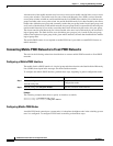
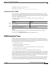
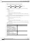
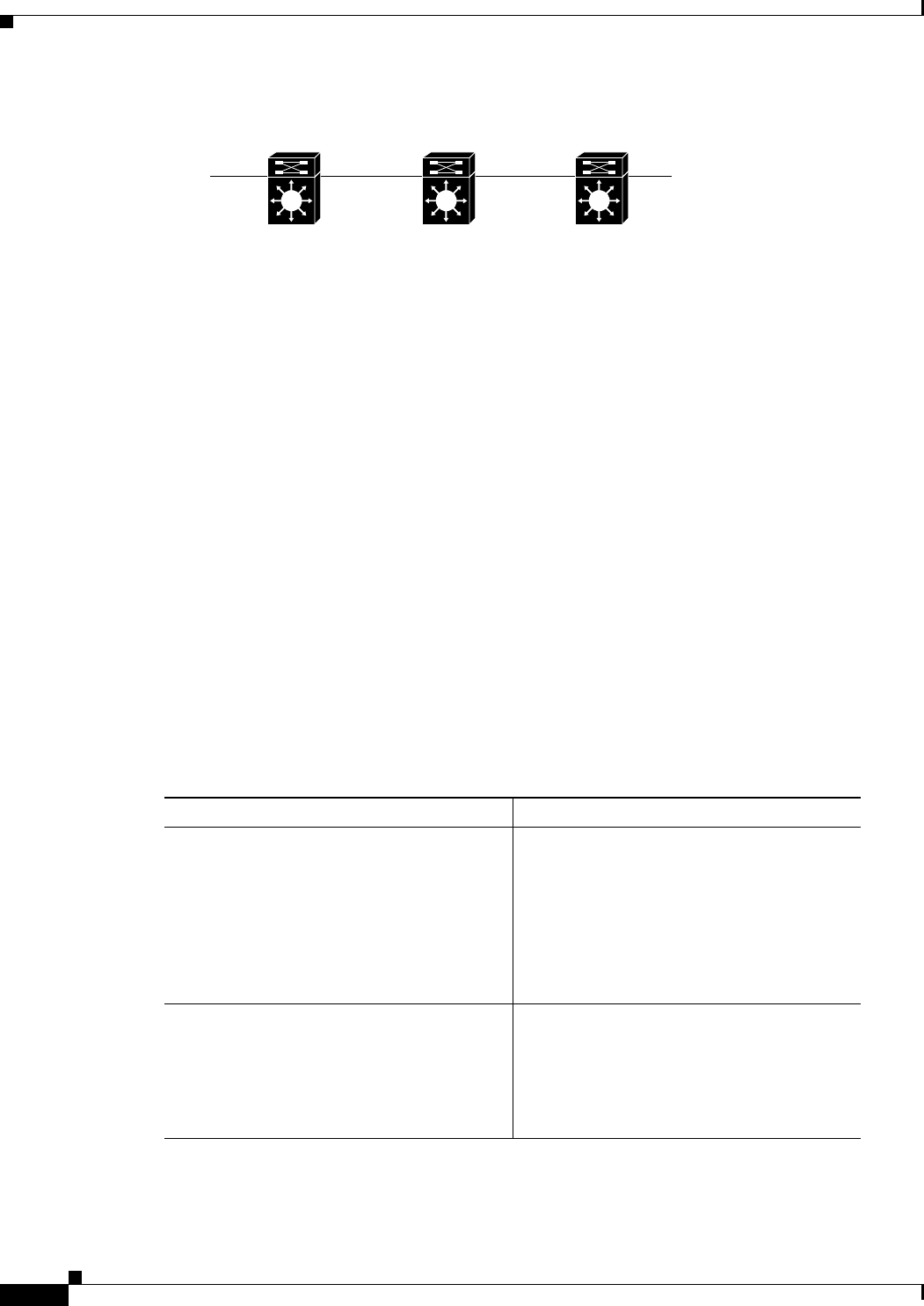
Figure 11-3 SVC with Connection Trace Initiated from I2 on Switch 2
If the direction of the trace is chosen as outgoing from switch 2, the trace returns the following
information:
• Switch 2
–
Outgoing: Interface I2
• Switch 3
–
Incoming: VPI value on NNI-B; VCI value on NNI-B
–
Outgoing: VPI value on NPI-2; VCI value on NPI-2; zero port-ID for non-PNNI interface;
interface NPI-2
If, however, the direction on interface I2 is chosen as incoming into switch 2, the trace proceeds in the
reverse direction. In this case, the trace returns the following information:
• Switch 2
–
Incoming: VPI value on NNI-B; VCI value on NNI-B
–
Outgoing: Interface I3
• Switch 1
–
Incoming: VPI value on NNI-A; VCI value on NNI-A
–
Outgoing: VPI value on NPI-1; VCI value on NPI-1; zero port-ID for non-PNNI interface;
interface NPI-1
To initiate a trace connection on a PNNI interface connection, use one of the following commands in
EXEC configuration mode:
NPI-1 NPI-2
SW-1 SW-2 SW-3
I1 I2I3
NNI-A NNI-B
68506
Command Purpose
atm pnni trace connection interfaces
atm slot/subslot/port
{direction {incoming | outgoing}
{call-reference value [endpt-reference
value] | {vpi vpi [vci vci]} [endpt-reference
value]} [age-timeout {seconds | none}]
[call-reference-trace] [connection-id-trace]
[fail-timeout seconds] [no-pass-along]
Configures ATM PNNI connection trace.
atm pnni trace connection interfaces
serial card/subcard/port:cgn
dlci number
[age-timeout {seconds | none}]
[call-reference-trace] [connection-id-trace]
[fail-timeout seconds] [no-pass-along]
Configures Frame Relay PNNI connection
trace.