


7-14
ATM Switch Router Software Configuration Guide
OL-7396-01
Chapter 7 Configuring Virtual Connections
Configuring Point-to-Multipoint PVC Connections
Configuring Point-to-Multipoint PVC Connections
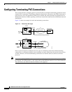
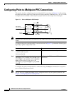
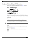
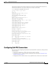
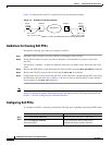
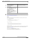
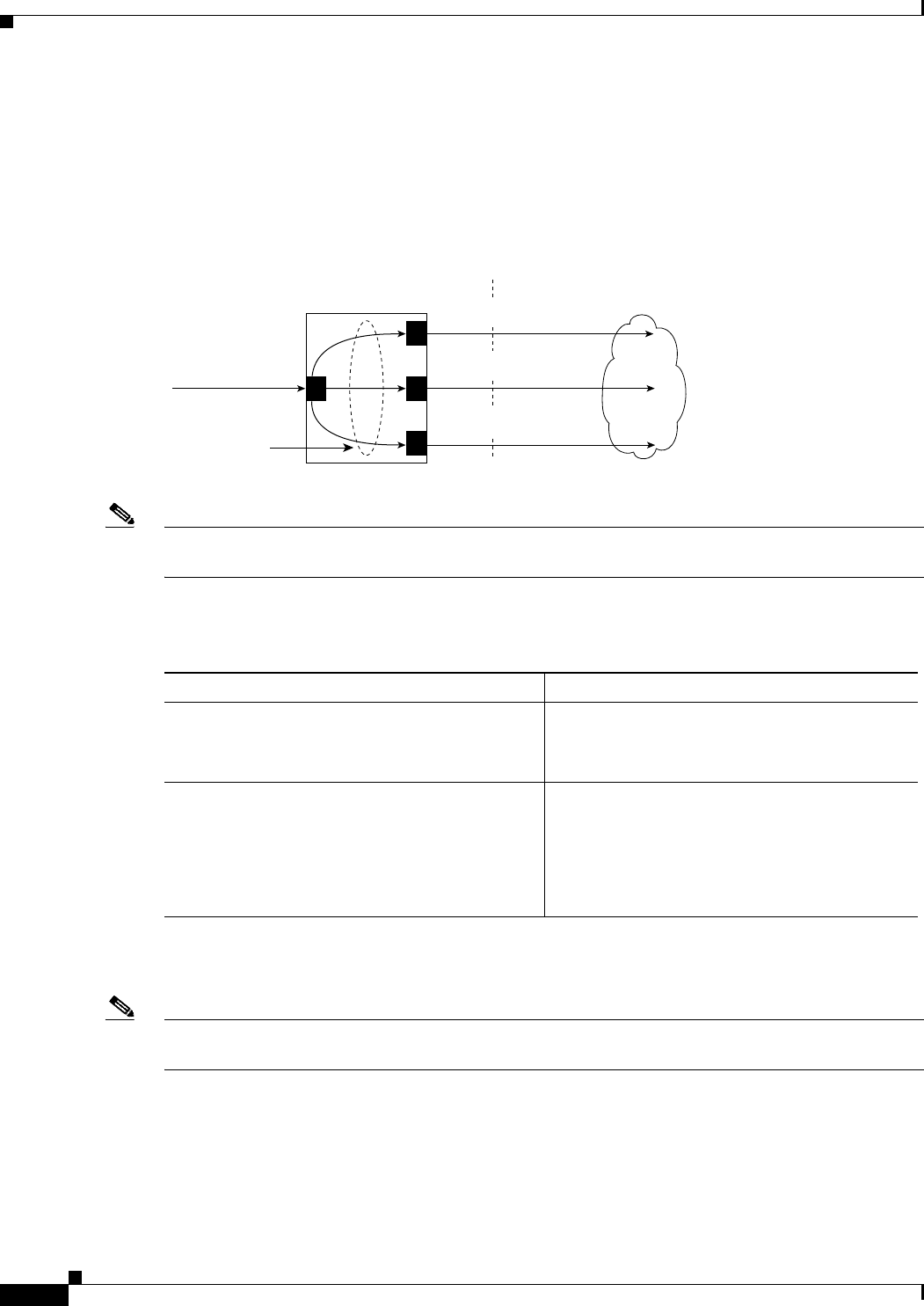
This section describes configuring point-to-multipoint PVC connections. In Figure 7-4, cells entering
the ATM switch router at the root point (on the left side at interface ATM 0/0/0, VPI = 50, VCI = 100)
are duplicated and switched to the leaf points (output interfaces) on the right side of the figure.
Figure 7-4 Point-to-Multipoint PVC Example
Note If desired, one of the leaf points can terminate in the ATM switch router at the route processor interface
ATM 0.
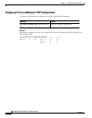
To configure the point-to-multipoint PVC connections shown in Figure 7-4, perform the following steps,
beginning in global configuration mode:
To configure the point-to-multipoint PVC connections using the atm pvc command, the root point is
port A and the leaf points are port B.
Note The row index for rx-cttr and tx-cttr must be configured before using this optional parameter. See
Chapter 9, “Configuring Resource Management.”
H6297
UNI or NNI
ATM
network
IF# = 0/1/1
VPI = 70, VCI = 210
IF# = 0/1/0
VPI = 60, VCI = 200
IF# = 0/0/0
V
PI = 50, VCI = 100
IF# = 0/1/2
VPI = 80, VCI = 220
Switch
fabric
Command Purpose
Step 1
Switch(config)# interface atm
card/subcard/port[.vpt#]
Switch(config-if)#
Selects the interface to be configured.
Step 2
Switch(config-if)# atm pvc vpi-A vci-A
[cast-type type-A] [rx-cttr index] [tx-cttr index]
[wrr-weight weight] [sched sched-A] interface
atm card/subcard/port[.vpt#] vpi-B vci-B
[cast-type type-B] [wrr-weight weight] [sched
sched-B]
Configures the PVC between ATM switch router
connections.