


11-46
ATM Switch Router Software Configuration Guide
OL-7396-01
Chapter 11 Configuring ATM Routing and PNNI
Advanced PNNI Configuration
Examples
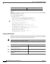
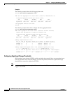
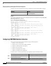
The following example shows the link aggregation mode:
Switch# show atm pnni aggregation link
PNNI PGL link aggregation for local-node 2 (level=72, name=Switch.2.72)
Configured aggregation modes (per service class):
CBR VBR-RT VBR-NRT ABR UBR
~~~~~~~~~~~ ~~~~~~~~~~~ ~~~~~~~~~~~ ~~~~~~~~~~~ ~~~~~~~~~~~
aggressive best-link best-link best-link best-link
No Aggregated links for this node.
Switch#
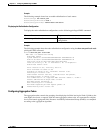
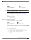
The following example shows how to display the node aggregation mode:
Switch# show atm pnni aggregation node
PNNI nodal aggregation for local-node 2 (level=56, child PG level=60)
Complex node representation, exception threshold: 60%
Configured nodal aggregation modes (per service class):
CBR VBR-RT VBR-NRT ABR UBR
~~~~~~~~~~~ ~~~~~~~~~~~ ~~~~~~~~~~~ ~~~~~~~~~~~ ~~~~~~~~~~~
best-link best-link best-link best-link aggressive
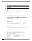
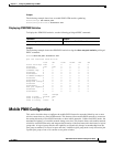
Summary Complex Node Port List:
Port ID Rem Inn Agg-Token Border Cnt In-Spoke Out-Spoke Agg-Accur
~~~~~~~~ ~~~~~~~ ~~~~~~~~~~ ~~~~~~~~~~ ~~~~~~~~~ ~~~~~~~~~ ~~~~~~~~~~
21FB000 12 0 1 default default ok
2371000 13 0 1 default default ok
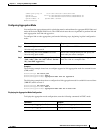
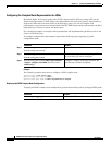
Summary Complex Node Bypass Pairs List (exception bypass pairs only)
/~~~~~~~~ LOWER PORT ID ~~~~~~~~\ /~~~~~~~~ HIGHER PORT ID ~~~~~~~\
Port ID Rem Inn Agg-Token Inacc Port ID Rem Inn Agg-Token Inacc Exceptns
~~~~~~~~ ~~~~~~~ ~~~~~~~~~~ ~~~~~ ~~~~~~~~ ~~~~~~~ ~~~~~~~~~~ ~~~~~ ~~~~~~~~
21FB000 12 0 no 2371000 13 0 no fwd rev
Configuring Significant Change Thresholds
PNNI topology state elements (PTSEs) would overwhelm the network if they were transmitted every
time any parameter in the network changed. To avoid this problem, PNNI uses significant change
thresholds that control the origination of PTSEs.
Note Any change in administrative weight (AW) and cell loss ratio (CLR) is considered significant and
triggers a new PTSE.