


19-48
ATM Switch Router Software Configuration Guide
OL-7396-01
Chapter19 Configuring Circuit Emulation Services
Configuring T1/E1 CES SVCs
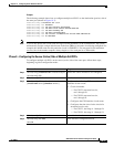
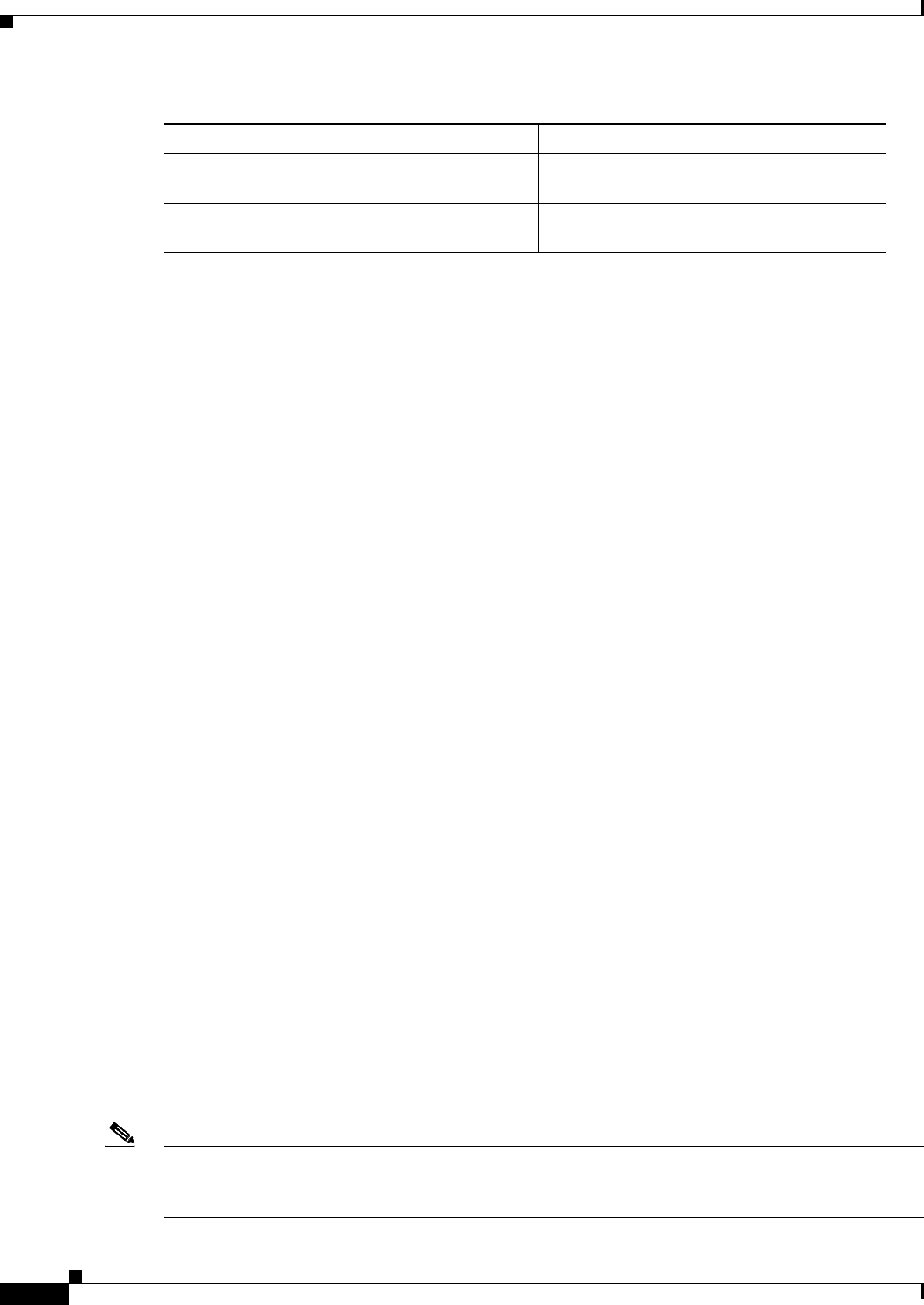
Examples
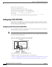
The following example shows how to display the basic information about the switched VC shown in
Figure 19-8, using the show ces circuit command:
Switch# show ces circuit
Interface Circuit Circuit-Type X-interface X-vpi X-vci Status
CBR0/0/0 0 Active SVC ATM-P0/0/3 0 1040 UP
CBR0/0/1 0 Passive SoftVC ATM-P0/0/3 0 16 UP
The output from this command verifies the source (CBR 0/0/0) and destination (CBR 0/0/1) port IDs of
the switched VC and indicates that the circuit is up.
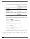
The following example shows how to display detailed information about the switched VC shown in
Figure 19-8, using the show ces circuit interface command:
Switch# show ces circuit interface cbr 0/0/0 0
Circuit: Name CBR-SVC-A, Circuit-state ADMIN_UP / oper-state UP Interface CBR0/0/0,
Circuit_id 0, Port-Type T1, Port-State UP
Port Clocking network-derived, aal1 Clocking Method CESIWF_AAL1_CLOCK_SYNC
Channel in use on this port: 1-24
Channels used by this circuit: 1-24
Cell-Rate: 4107, Bit-Rate 1544000
cas OFF, cell_header 0x100 (vci = 16)
Configured CDV 2000 usecs, Measured CDV 331 usecs
De-jitter: UnderFlow 0, OverFlow 0
ErrTolerance 8, idleCircuitdetect OFF, onHookIdleCode 0x0
state: VcAlarm, maxQueueDepth 823, startDequeueDepth 435
Partial Fill: 47, Structured Data Transfer 0
Active SVC
Src: atm addr 47.0091.8100.0000.0004.ddec.d301.4000.0c80.0030.10 vpi 0, vci 16
Dst: atm addr 47.0091.8100.0000.0004.ddec.d301.4000.0c80.0034.10
The output from this command verifies the following configuration information:
• The circuit named CBR-SVC-A is in an UP state.
• The interface CBR 0/0/0 has a circuit id of 0 (because the entire bandwidth of the port is dedicated
to that circuit).
• The source port for the switched VC is CBR 0/0/0. The Dst (destination) ATM address is
47.0091.8100.0000.0004.ddec.d301.4000.0c80.0034.10.
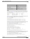
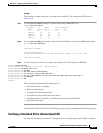
Configuring T1/E1 Structured CES SVCs
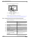
Figure 19-9 shows an example of a switched VC configured for structured CES.
Note Typically you configure a switched VC between CES modules anywhere in your network. For simplicity,
this example and the accompanying procedure describe how to create a switched VC between modules
in the same ATM switch router chassis.
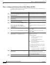
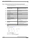
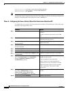
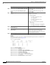
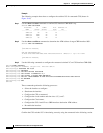
Command Purpose
show ces circuit Shows configuration information for the
switched VC.
show ces circuit interface cbr card/subcard/port
circuit-id
Shows detailed interface configuration
information for the switched VC.