


DEFINITY Enterprise Communications Server Release 8.2
Upgrades and Additions for R8r
555-233-115
Issue 1
April 2000
Upgrading R5si/R6si to R8r EPN and Adding Memory
3-28Release 5/6si to Release 8r
3
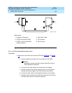
For a high reliability system with 2 DS1 Conv-remoted expansion port networks,
this arrangement requires:
■ 6 DS1 Converter circuit packs (TN1654)
■ 6 DS1 Converter-to-EI cables (846448637 and/or 846448645)
■ 6 H-600-348 cables
■ 3, 6, 9, or 12 pairs of CSUs
■ 3, 6, 9, or 12 pairs of wall-field cables (provided with CSUs)
For 1 or 2 Collocated Expansion Port Networks
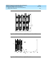
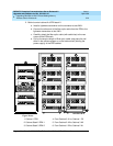
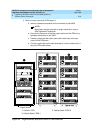
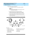
1. Behind port carrier C of the multicarrier PPN. See Figure 3-9 and Figure
3-10:
a. Install a lightwave transceiver on the connector at slot 1C02.
NOTE:
Attenuators may be required for single mode fiber using a
300A Lightwave Transceiver
b. Connect 1 end of the appropriate fiber optic cable to the lightwave
transceiver at slot 1C02.
c. Route the fiber optic cable from the lightwave transceiver to the
cabinet’s cable tray and down, out of the cabinet, to the EPN stack.
d. Carefully attach the fiber optic cable (with cable ties) to the wall of
the cable tray at the built-in cable tie positions.
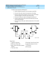
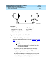
2. Behind control cabinet A EPN stack 2:
a. Install a lightwave transceiver on the connector at slot 2A01.
NOTE:
Attenuators may be required for single mode fiber using a
300A Lightwave Transceiver
b. Connect the other end of the fiber optic cable from the PPN to the
lightwave transceiver at slot 2A01.
c. Carefully attach the fiber optic cable (with cable ties) to the rear
covers of the EPN stack.
d. Coil up the surplus fiber optic cable, and place the coil either in the
cable manager or on the bottom shelf (holding the power supply) of
the PPN cabinet.