


DEFINITY Enterprise Communications Server Release 8.2
Upgrades and Additions for R8r
555-233-115
Issue 1
April 2000
Adding or Removing Cabinet Hardware
6-96Add a Switch Node Carrier (Standard Reliability)
6
Shut Down DEFINITY AUDIX System
1. Shut down the AUDIX assembly and allow the disk to completely spin
down. Refer to
‘‘DEFINITY AUDIX Power Procedures’’ on page 6-141
.
!
WARNING:
Neglecting to shut down an AUDIX assembly before powering down
the system cabinet where it resides can damage the AUDIX disk.
2. Unseat the AUDIX assembly from its backplane connectors.
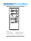
Power Down Cabinet
1. At the cabinet that is receiving the new switch node carrier, set the main
circuit breaker to OFF.
Remove Doors
1. Remove the front and rear doors from the cabinet where the switch node
carrier will be installed.
Disconnect Ground Cables
Skip these steps if a switch node carrier is being added to an empty carrier
position.
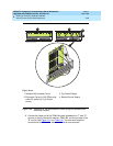
1. Label the ground cables associated with the port carrier to be removed.
2. Disconnect the ground cables from the top of the port carrier to be
removed. Allow the cables to hang down for now.
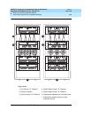
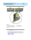
Remove Circuit Packs from Port Carrier D
Skip these steps if a switch node carrier is being added to an empty carrier
position.
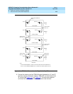
1. To ensure that circuit packs and power units in the “D” carrier are properly
replaced, label each component with its slot number.
2. Disconnect the power cords from the power units in the “D” carrier.
3. Remove all circuit packs and power units from carrier “D.” Store the circuit
packs in static-proof packaging.
4. Remove the circuit pack blanks from slots that do not contain circuit
packs.
5. Remove the front trim plate from the “D” carrier by pulling it straight off.