


DEFINITY Enterprise Communications Server Release 8.2
Upgrades and Additions for R8r
555-233-115
Issue 1
April 2000
Multicarrier G2 Universal Module to R8r EPN
5-92Critical Reliability
5
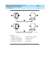
Fiber-Remoted Port Networks
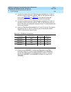
For a critical reliability system with 1 fiber-remoted EPN, use 4 fiber optic cables,
4 lightwave transceivers, and 4 lightguide interconnect units (provided by the
PSC). For a critical reliability system with 2 fiber-remoted EPNs, use 12 fiber optic
cables, 12 lightwave transceivers, and 12 lightguide interconnect units (provided
by the PSC).
For fiber-remoted cabinets, route the cables down the cable tray and out the
bottom of the cabinet to the MDF to the lightguide interconnect units.
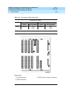
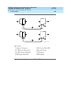
For Either 1 or 2 Collocated Expansion Port Networks
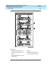
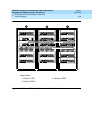
1. At control carrier A of PPN cabinet 1 (see Figure 5-28 through Figure
5-31):
■ Install a lightwave transceiver on the cable connector at slot 1A01.
■ Connect a fiber optic cable to the transceiver just installed.
■ Carefully attach the fiber optic cable (with cable ties) to the wall of
the cable tray at the built-in cable tie positions.
2. Behind control carrier A of EPN cabinet 2:
■ Install a lightwave transceiver on the cable connector at slot 2A01.
■ Connect the other end of the fiber cable to the transceiver just
installed.
■ Carefully attach the fiber optic cable (with cable ties) to the wall of
the cable tray at the built-in cable tie positions.
■ At the top of the cabinet, coil the surplus fiber optic cable and
attach it to the wall of the cable tray.
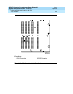
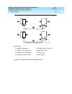
3. Behind control carrier B of PPN cabinet 1:
■ Install a lightwave transceiver on the cable connector at slot 1B01.
■ Connect a fiber optic cable to the transceiver just installed.
■ Carefully attach the fiber optic cable (with cable ties) to the wall of
the cable tray at the built-in cable tie positions.
4. Behind port carrier B of EPN cabinet 2:
■ Install a lightwave transceiver on the cable connector at slot 2B02.
■ Connect the other end of the fiber cable to the transceiver just
installed.
■ Carefully attach the fiber optic cable (with cable ties) to the wall of
the cable tray at the built-in cable tie positions.
■ At the top of the cabinet, coil the surplus fiber optic cable and
attach it to the wall of the cable tray.