DEFINITY Enterprise Communications Server Release 8.2
Upgrades and Additions for R8r
555-233-115
Issue 1
April 2000
Adding or Removing Cabinet Hardware
6-59Add IP Interface Assembly
6
Connect the Modem
NOTE:
These instructions are for connecting the U.S. Robotics modem supplied to
U.S. customers only. If using a different modem, follow the manufacturer’s
instructions on connecting the modem.
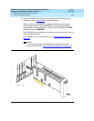
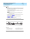
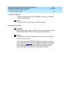
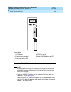
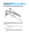
1. Connect the RS232 port of the modem to the MODEM connector of the
TN802B external cable assembly.
NOTE:
Check the labels near the connectors; the MODEM and COM2
connectors look the same.
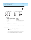
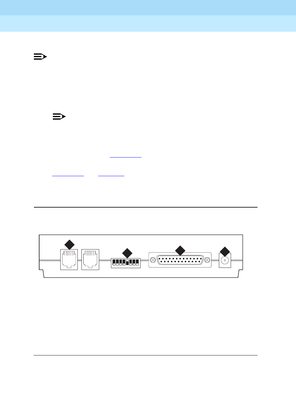
2. Connect an analog telephone line to the leftmost analog-line port on the
modem as shown in
Figure 6-25
.
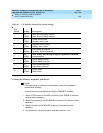
3. Make sure that the modem’s DIP switches are set as shown in
Figure 6-25
and
Table 6-7
.
4. Plug the modem into an AC power outlet.
5. Turn on the modem using the switch on the front of the modem.
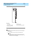
Figure 6-25. External Modem Connections for U.S. Robotics Sporster
Figure Notes
1. Connect analog line here.
2. DIP switch 5 must be up.
3. Connect MODEM connector here.
4. Connect power connector here.
12345678
modfrobo KLC 030499
2
3
4
1


