


DEFINITY Enterprise Communications Server Release 8.2
Upgrades and Additions for R8r
555-233-115
Issue 1
April 2000
Multicarrier G2 Universal Module to R8r EPN
5-54High Reliability
5
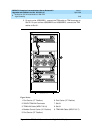
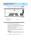
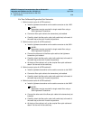
12. Install the front trim plate on the “A” carrier.
13. Install the power units (removed from G2 module control carrier) into the
“A” carrier. Do not interchange the physical locations of the units. The
631AR1, 631WA1, 631DA1, or 644A install in the left side, while the
631BR1, 631WB1, 631DB1, or 645B install in the right side.
NOTE:
In most cases, the new Release 8 carrier will contain the same power
supplies as in the existing system. However, the new Release 8
carrier may contain a 649A Power Unit. If so, use the power units
from the G2 power module.
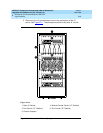
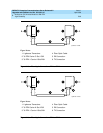
14. If the expansion control carrier contains a 631BR1, 631WB1, or 645B
power unit, install the previously removed TN736 power unit in port slots
“18” and “19” of the carrier (adjacent to the 631BR1, 631WB1, or 645B). If
the system is equipped for neon message waiting, a TN752 or TN755
power unit must be used.
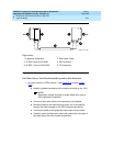
NOTE:
The TN736 is not required when the 631DB1 or 645B power unit is
used in the J58890AH control carrier or the J58890BB-2 or
J58890BB-3 port carriers. It is required in the J58890BB-1 port
carrier, regardless of which 631 power unit is provided. Use the
TN752 or TN755 if the system is equipped with neon message
waiting.
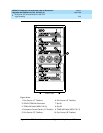
15. Connect the white power cords to the power units.
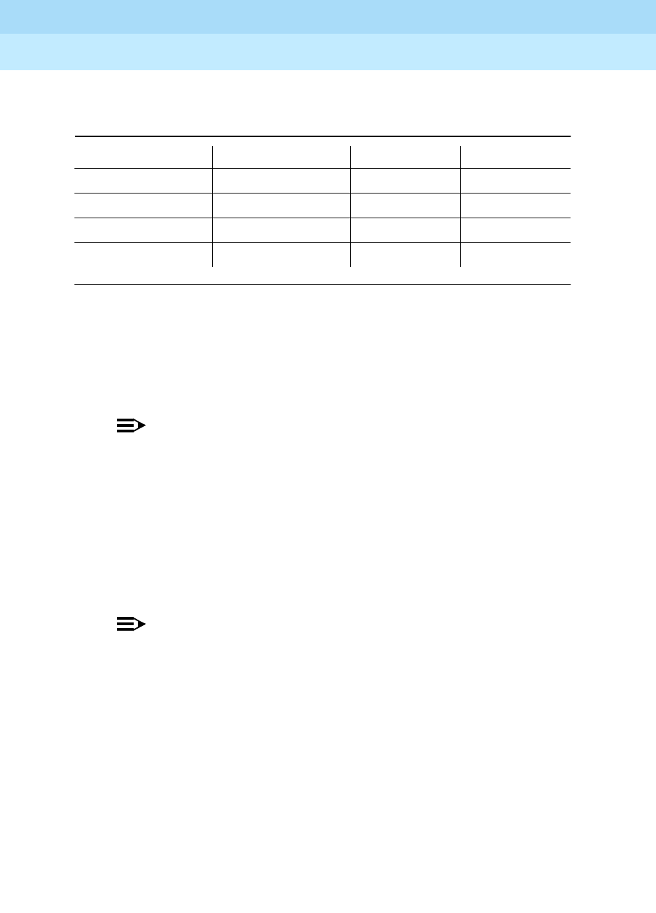
Table 5-11. TDM/LAN Connections
"J" Number Carrier Type LHS Slot RHS Slot
J58890BB-1 Port 21 02
J58890BB-2 Port 21 01
J58890BB-3 Port 21 01
J58890AF EPN Control “A” 21 02