


DEFINITY Enterprise Communications Server Release 8.2
Upgrades and Additions for R8r
555-233-115
Issue 1
April 2000
Adding or Removing Cabinet Hardware
6-90Add a Control Carrier (Add Duplication)
6
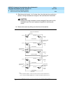
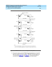
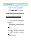
10. Connect the loose end of the TDM/LAN cable (between the “C” and “B”
carriers) to the pin-field block marked “TDM/LAN” on the right side of the
“B” carrier (See
Figure 6-31
and
Table 6-8
). The other end remained
connected to the “C” carrier when the old carrier was removed.
11. Connect the loose end of the TDM/LAN cable (between the “A” and “B”
carriers) to the pin-field block marked “TDM/LAN” on the left side of the
“B” carrier (See
Figure 6-31
and
Table 6-8
). The other end remained
connected to the “A” carrier when the old carrier was removed.
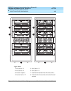
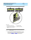
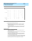
12. Install the alarm duplication cable (H600-198 G1) between carriers “B”
and “A.” Connect the cable to the “ICCA” pin-field block (to the right of the
pin-field block for slot “00”) of both carriers. See
Figure 6-32
. Connect the
“UAK” (upper) connector to carrier “B,” and connect the “LAK” (lower)
connector to carrier “A.”
!
CAUTION:
While installing the ICC cable connectors, be careful not to bend any
backplane pins. Double check each connection to verify that the
pins are straight.
NOTE:
With a connector in each hand, flex the wires within the cable’s
sheath to form a usable C-shaped cable.
13. Install the ICCC cable (H600-182 G1) between carriers “B” and “A.”
Connect the cable to the “ICCC” pin-field block (behind slot “01”) of both
carriers. See
Figure 6-32
.
14. Install the duplication cable (WP91954 L1) between carriers “B” and “A.”
Connect the cable to the “ICCD” pin-field block (behind slot “02”) of both
carriers. See
Figure 6-32
.
NOTE:
The duplication cable’s connectors are keyed to ensure proper
positioning on the pin-field block.
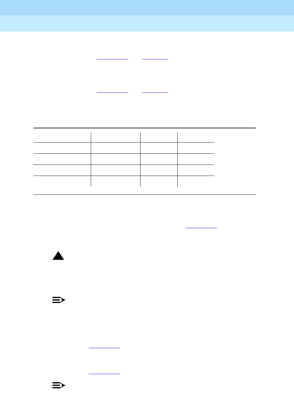
Table 6-8. TDM/LAN Connections
“J” Number Carrier Type LHS Slot RHS Slot
J58890BB L1 Port 21 02
J58890BB L2 Port 21 01
J58890BB L3 Port 21 01
J58890AP Control 21 02