


DEFINITY Enterprise Communications Server Release 8.2
Upgrades and Additions for R8r
555-233-115
Issue 1
April 2000
Multicarrier G2 Universal Module to R8r EPN
5-32Standard Reliability
5
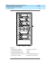
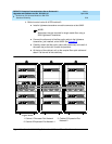
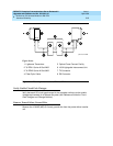
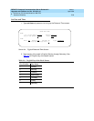
Figure 5-8. Collocated Fiber Optic Connections EPN1 to EPN2
For Either One or Two Fiber-Remoted Expansion Port Networks
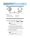
1. At control carrier A of PPN cabinet 1. See Figure 5-5 through Figure 5-9.
■ Install a lightwave transceiver on the cable connector at slot 1A01.
NOTE:
Attenuators may be required for single mode fiber using a
300A Lightwave Transceiver
■ Connect a fiber optic cable to the transceiver just installed.
■ Route the cable to the cable tray and down, out of the cabinet,
through the cable manager to the PDS cross-connect facility.
■ Connect the fiber cable to the lightguide interconnect unit provided.
■ Carefully attach the cable (with cable ties) to the wall of the cable
tray at the built-in cable tie positions.
2. Behind control carrier A of EPN cabinet 2:
■ Install a lightwave transceiver on cable connector at slot 2A01.
NOTE:
Attenuators may be required for single mode fiber using a
300A Lightwave Transceiver
■ Connect a fiber optic cable to the transceiver just installed.
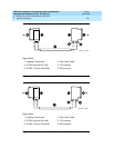
Figure Notes
1. Lightwave Transceiver
2. To PPN Carrier A Slot 2A02
3. To EPN 1 Carrier A Slot 3A02
4. Fiber Optic Cable
5. TX Connector
6. RX Connector
cydff05 CJL 10319
6
RX TX
2211