DEFINITY Enterprise Communications Server Release 8.2
Upgrades and Additions for R8r
555-233-115
Issue 1
April 2000
Adding or Removing Cabinet Hardware
6-146Installing a 3150/3170 Channel Service Unit
6
Installing a 3150/3170
Channel Service Unit
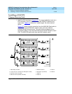
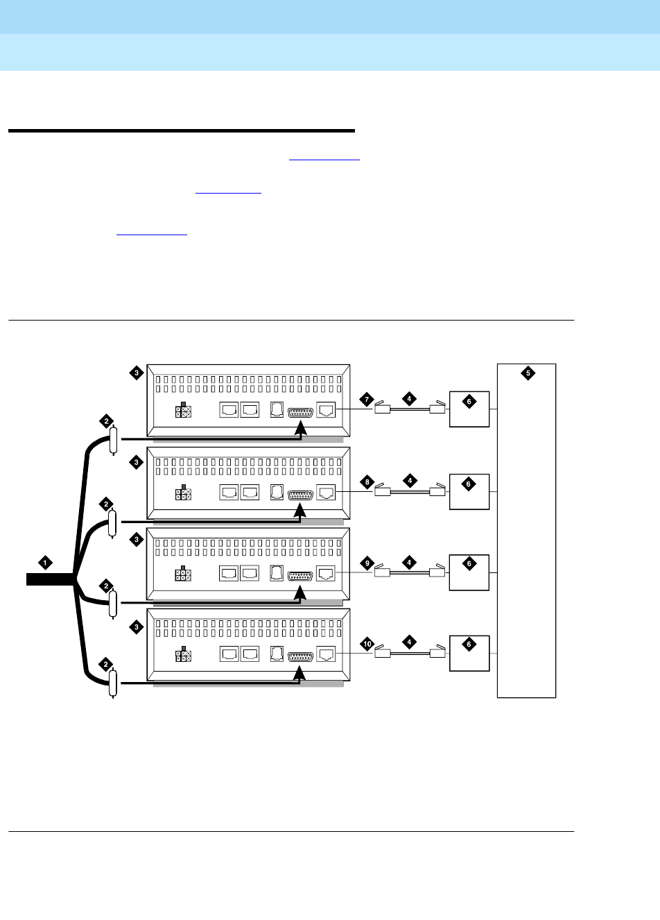
1. Install the CSU as shown in Figure 6-57. For some installations (such as a
DS1 converter), use a Y-cable to connect the DEFINITY System to the
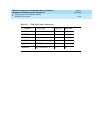
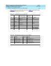
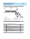
quad cable. Table 6-14
shows the Y-cable lengths. Be sure to label all
cables.
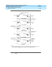
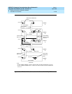
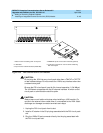
Figure 6-57
shows a typical connection from the H600-348 Quad cable to
the CSU, through the H600-307 network cable, and to the network
interface through the smart jacks. The quad cable provides up to four
connections using a 15-pin connector that plugs into the DTE jack on each
CSU. The H600-348 quad cable may require an adapter cable.
Figure 6-57. 3150/3170 Channel Service Unit Connections
1. H600-348 quad cable
2. 15-pin male “D” connectors (to DTE jacks on CSU)
3. Channel service unit (CSU)
4. H600-307 cable (RJ-48C to RJ-48C)
5. Network interface
6. Smart jack (if provided)
7. Cable A
8. Cable B
9. Cable C
10. Cable D
3150csu RBP 062696
POWER
AUX PORT COM PORT MODEM
DTE
NETWORK
POWER
AUXPO RT COMPORT MOD EM
DTE
NETWORK
POWER
AUX PORT COMPORT MODEM
DTE
NETWORK
POWER
AUXPORT COMPORT MODEM
DTE
NETWORK


