


DEFINITY Enterprise Communications Server Release 8.2
Upgrades and Additions for R8r
555-233-115
Issue 1
April 2000
Adding or Removing Cabinet Hardware
6-104Add a Switch Node Carrier (Standard Reliability)
6
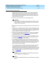
Install Circuit Packs
1. Install the new circuit packs into carrier “D.” Use the decal and the
upgrade configuration document (provided with the equipment) as a
guide.
2. Install circuit pack blanks in slots not equipped with circuit packs.
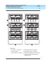
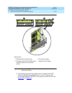
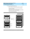
Interconnect Port Networks
1. Behind the cabinet containing the switch node carrier (See
Figure 6-37
):
a. Connect the metallic intracarrier cable (H600-278) to slots 1D01
and 1D02.
2. Behind switch node carrier D of PPN cabinet 1 (See
Figure 6-37
):
a. For each EPN, install 1 lightwave transceiver on a cable connector
with the following order of slots: 1D20, 1D03, 1D19, 1D04, 1D18,
1D05, and so forth.
b. Connect 1 end of a fiber optic cable to each lightwave transceiver,
just installed.
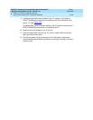
c. Carefully attach the fiber optic cables (with cable ties) to the wall of
the cable tray at the built-in cable-tie positions.
3. Behind processor carrier A of each EPN cabinet:
a. Install a lightwave transceiver on cable connector at slot 1A01.
b. Connect the other end of the fiber optic cable to the lightwave
transceiver, just installed, at slot A01.
c. Carefully attach the fiber optic cable (with cable ties) to the wall of
the cable tray at the built-in cable-tie positions.
d. Coil up the surplus length of fiber optic cable, and carefully attach
the coil to the wall of the cable tray.
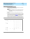
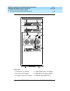
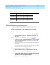
Table 6-9. TDM/LAN Connections
“J” Number Carrier Type LHS Slot RHS Slot
J58890BB L1 Port 21 02
J58890BB L2 Port 21 01
J58890BB L3 Port 21 01
J58890AP Control 21 02