DEFINITY Enterprise Communications Server Release 8.2
Upgrades and Additions for R8r
555-233-115
Issue 1
April 2000
Multicarrier G2 Universal Module to R8r EPN
5-85Critical Reliability
5
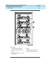
12. Connect the loose end of the TDM/LAN cable (between the “A” and “D”
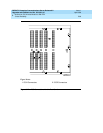
carriers) to the pin-field block marked “TDM” on the right side of the “A”
carrier (see
Figure 5-26
and
Table 5-15
). The other end remained
connected to the “D” carrier when the old carrier was removed.
13. Connect the loose end of the TDM/LAN cable (between the “B” and “C”
carriers) to the pin-field block marked “TDM” on the right side of the “B”
carrier. The other end remained connected to the “C” carrier when the old
carrier was removed.
14. Install the TDM/LAN cable between the “A” and “B” carriers. The cable is
connected to the “A” and “B” carriers at the pin-field blocks marked
“TDM” on the left side of each carrier.
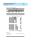
15. On port carrier J58890BB-1, connect the TDM cable or the TDM
terminator to Slot 02. On port carriers J58890BB-2 and J58890BB-3,
connect the TDM cables or the TDM terminator to Slot 01. If the port
carrier has J58890BB-1
and
J58890BB-2 printed on it, treat it as a
J58890BB-1.
Table 5-15. TDM/LAN Connections
"J" Number Carrier Type LHS Slot RHS Slot
J58890BB-1 Port 21 02
J58890BB-2 Port 21 01
J58890BB-3 Port 21 01
J58890AF EPN Control “A” 21 02


