


DEFINITY Enterprise Communications Server Release 8.2
Upgrades and Additions for R8r
555-233-115
Issue 1
April 2000
Adding or Removing Cabinet Hardware
6-97Add a Switch Node Carrier (Standard Reliability)
6
Remove Port Carrier D
Skip these steps if a switch node carrier is being added to an empty carrier
position.
NOTE:
Note the position of the TDM/LAN cables before disconnecting.
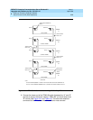
1. If a switch node carrier is being installed in the “D” position of an EPN,
remove the TDM/LAN cable from between the “D” and “A” carriers.
For other EPNs or the PPN, disconnect 1 end of the TDM/LAN cable
(between the “D” and “A” carriers) from the “D” carrier.
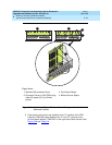
2. Remove the ZAHF4 TDM/LAN bus terminator from slot “21” of the “D”
carrier.
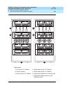
3. Disconnect 1 end of the 8 ground straps (between the “D” and “E”
carriers) from the “D” carrier (See
Figure 6-33
). These straps will be
reconnected to the new “D” carrier.
4. Disconnect the 8 ground straps from the "D" carrier (between the “D” and
“A” carriers or the "D" carrier and the enhanced fan unit—see
Figure 6-33
).
Reconnect the 8 ground straps to the "D" carrier.
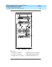
5. Disconnect the “P1” (small 9-pin) connector from the “D” carrier. Move the
cable into a position where it will not interfere with removing the carrier.
6. Remove the 4 screws (top 2 first) holding the “D” carrier to the cabinet
frame. Use a long-handle screwdriver or 5/16-inch socket with a 10-inch
extension.
7. Behind the “D” carrier in a “DEFINITY style” cabinet, remove the 2 screws
holding the “D” carrier to the cabinet frame.
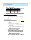
8. Slide the carrier forward 1 to 2 inches; then, from the back, be sure that no
cables or wiring harnesses are caught on the cabinet/carrier framework.
!
CAUTION:
Cables and wiring harnesses can be damaged if they catch on the
framework and if too much pressure is applied in removing the
carrier.
9. Remove the carrier by sliding it out the front of the cabinet.