


DEFINITY Enterprise Communications Server Release 8.2
Upgrades and Additions for R8r
555-233-115
Issue 1
April 2000
Multicarrier G2 Universal Module to R8r EPN
5-22Standard Reliability
5
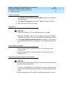
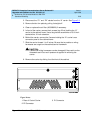
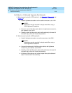
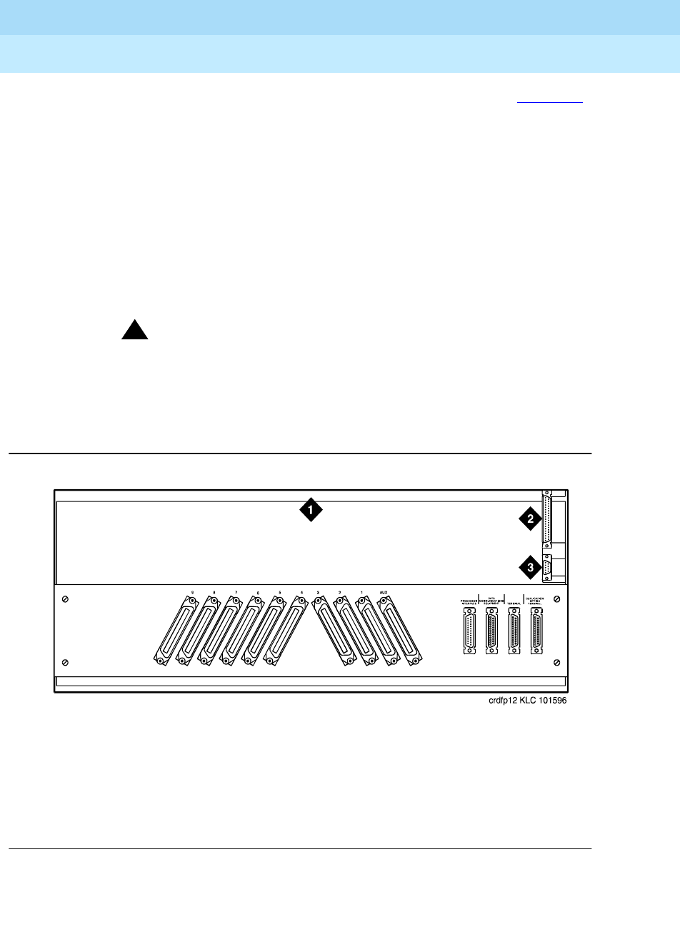
2. Disconnect the “P1” and “P2” cables from the “A” carrier. See
Figure 5-3
.
3. Remove the fan trim plate by pulling it straight off.
4. Clean or replace the air filter (403326820) if necessary.
5. In front of the carrier, remove the 4 screws (top 2 first) holding the “A”
carrier to the cabinet frame. Use a long-handle screwdriver or 5/16-inch
socket with a 10-inch extension.
6. Behind the carrier, remove the 2 screws holding the “A” carrier’s rear
connector panel to the cabinet frame.
7. Slide the carrier forward 1 to 2 inches. Be sure that no cables or wiring
harnesses are caught on the cabinet/carrier framework.
!
CAUTION:
Cables and wiring harnesses can be damaged if they catch on the
framework and if too much pressure is applied in removing the
carrier.
8. Remove the carrier by sliding it out the front of the cabinet.
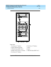
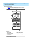
Figure 5-3. Location of P1 and P2 Connectors
Figure Notes
1. Rear of Control Carrier
2. P2 Connector
3. P1 Connector