


DEFINITY Enterprise Communications Server Release 8.2
Upgrades and Additions for R8r
555-233-115
Issue 1
April 2000
Adding or Removing Cabinet Hardware
6-144Installing an Integrated Channel Service Unit (ICSU) Module
6
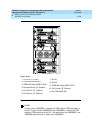
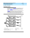
4. Secure the 4C retainer around the 120A.
5. Attach the supplied H600-383 cable to the 120A and to the network smart
jack.
This cable is directional. To determine the end that connects to the 120A,
perform a continuity test between pins 3 and 7. The end with this
continuity is the 120A end. The shield is grounded only at the 120A end.
Use the cable provided. If cabling other than that provided with the 120A
is used, observe the following guidelines:
■ Use 24-gauge wire that provides individually shielded, twisted pairs
for transmit and receive signals. Use the cable between the
network interface and the 120A. Ground the shields of this cable
only at the 120A end to avoid ground loops.
■ Cabling between the network interface and 120A can have no
bridge taps.
■ If using standard house riser cable for connections between the
network interface and the 120A, maintain a 100-pair separation
between the receive and transmit twisted pairs.
■ If using standard house riser cable for connections between the
network interface and the 120A, allow no more than 2 cross
connects to 110-type cross connect blocks.
■ Never use quad cable (untwisted two pair telephone cable) in a
DS1 line.
■ Avoid mixing wires of different gauges in a DS1 line.
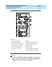
6. If using external alarm equipment, attach the supplied DW8 cable to the
120A and the external equipment. The maximum length of this cable
depends on the alarm equipment.
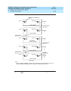
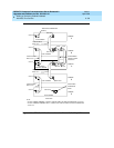
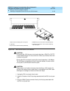
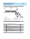
7. If a TN474F is used, make sure the circuit pack is set for 24-channel
operation. Set the switch on the circuit pack as shown in Figure 2-1.
8. From the DS1 circuit-pack screen of the system administration console,
set the line compensation field to 0-133 feet (40.6 m).
9. Reset the 120A by reseating the DS1 circuit pack.
When you reinsert the DS1 circuit pack after installing a 120A CSU the
120A resets. The DS1 circuit pack initializes and tests the 120A. When
initialization and testing is complete, the green LED goes off. If the RED
indicator is OFF after the test, the ICSU is working.
10. If the circuits do not pass the self test, troubleshoot the 120A as instructed
in
Integrated CSU Module Installation and Operation
.