


Chapter 3
Understanding the Digitizer
Chapter Contents
This chapter contains the HP E1429 Digitizer description of operation.
Where applicable, the chapter relates the digitizer’s SCPI commands to the
digitizer hardware they control. The main sections of the chapter include:
• HP E1429A Digitizer Block Diagram. . . . . . . . . . . . . . . . . . 103
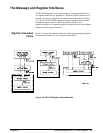
• The Message and Register Interfaces . . . . . . . . . . . . . . . . . . 105
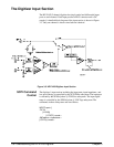
• The Digitizer Input Section . . . . . . . . . . . . . . . . . . . . . . . . . . 106
• Arming and Triggering . . . . . . . . . . . . . . . . . . . . . . . . . . . . . 111
• The Analog-to-Digital Converter . . . . . . . . . . . . . . . . . . . . . 129
• Data Flow, Storage, and Conversions . . . . . . . . . . . . . . . . . . 129
• Memory Management . . . . . . . . . . . . . . . . . . . . . . . . . . . . . . 142
• VME Bus Data Transfers. . . . . . . . . . . . . . . . . . . . . . . . . . . . 146
• Local Bus Data Transfers. . . . . . . . . . . . . . . . . . . . . . . . . . . . 156
• The Digitizer Status Registers . . . . . . . . . . . . . . . . . . . . . . . . 165
• Saving Digitizer Configurations . . . . . . . . . . . . . . . . . . . . . . 174
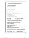
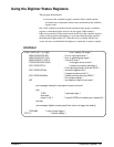
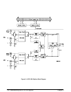
HP E1429 Digitizer Block Diagram
The HP E1429 Digitizer block diagram is shown in Figure 3-1. Channels 1
and 2 have their own input section and their own 12-bit,
20 MSample/second analog-to-digital (A/D) converter. The message
interface, register interface, trigger/timebase section, and memory are
common to both channels.
Chapter 3 Understandin
g
the HP E1429 Di
g
itizer 103