


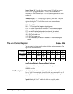
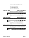
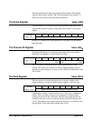

The Reference Oscillator Register base + 4F
16
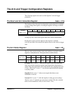
The reference oscillator register sets the reference source from which the
sample rate is derived. The register is also used to output synchronization
signals.
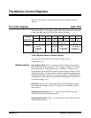
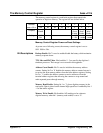
Address 7 6 5 4 3 2 1 0
base + 4F
16
128
64 32 16 8 4 2 1
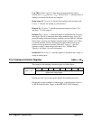
Purpose
Arm source
1 enable
ECLTrg1 source ECLTrg0 source Reference oscillator source
Setting
0 - enabled
1 - disabled
0 0 - 1 1 0 0 - 1 1 0 0 0 - 1 0 0
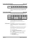
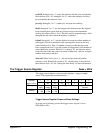
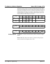
Reference Oscillator Register Power-on/Reset Settings
At power-on or following a reset, the reference oscillator register is set to
0111 1000 or 78
16
.
Bit Descriptions Arm source 1 enable: Setting bit 7 to ’0’ enables the arm source 1 trigger
source (arm source register: base + 49
16
) to arm the digitizer. Setting bit 7
to ’1’ disables arm source 1.
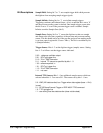
ECLTrg1 source: Bits 6 - 5 set the signal source that is output on the
ECLTrg1 trigger line. The sources include:
0 0 - a 25 ns wide negative-going pulse each time a convert pulse is sent
tothe A/D converter.
0 1 - reference oscillator as selected by bits 2 - 0. The falling edge is
synchronous with the rising edge of the internal 20 MHz oscillator, the
ECLTrg lines, CLK10, and is synchronous with the falling edge of an
external reference oscillator.
1 0 - reserved.
1 1 - off. Outputs an ECL high level which then allows ECLTrg1 to be used
as an input.
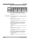
ECLTrg0 source: Bits 4 - 3 set the signal source that is output on the
ECLTrg0 trigger line. The sources include:
0 0 - a 25 ns wide negative-going pulse each time a convert pulse is sent
tothe A/D converter.
0 1 - reference oscillator as selected by bits 2 - 0. The falling edge is
synchronous with the rising edge of the internal 20 MHz oscillator, the
ECLTrg lines, CLK10, and is synchronous with the falling edge of an
external reference oscillator.
1 0 - reserved.
1 1 - off. Outputs an ECL high level which then allows ECLTrg1 to be used
as an input.
Appendix C Register Programming 359