


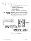

The high-speed internal (data) bus routes data between the A/D, digitizer
memory, the local bus, and the VME (VXI data transfer) bus (Figure 3-7).
There is no user-access to the high-speed internal bus.
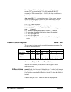
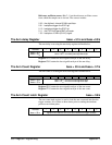
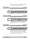
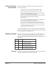
The Pulse Register base +08
16
The pulse register is a read/write register that generates high-speed clock
signals when the traffic register’s high-speed clock source is set to ’pulse
register’ .
Address 76543210
base + 08
16
register read/write: generates high-speed bus clock pulse
Reading, or writing to this register generates a clock pulse for the internal
high-speed bus.
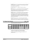
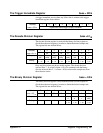
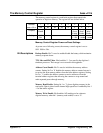
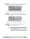
The Channel ID Register base +0A
16
The channel ID register is a read/write register that allows user-defined
identifiers to be appended to each channel’s readings.
Address 76543210
base + 0A
16
channel 1 ID
LSB MSB
channel 2 ID
LSB MSB
The ID assigned is represented by the 4 least significant bits of each
reading. The ID bits are not stored in memory with the readings, but are
appended to each reading as it is read over the VME (VXI data transfer) bus
or Local bus.
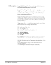
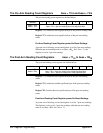
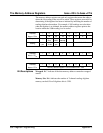
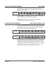
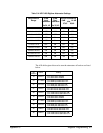
The Data Register base +0C
16
The data register is a read/write register used to retrieve readings from
digitizer memory or to retrieve them from the digitizer’s A/D converter.
Address 76543210
base + 0C
16
register read/write: retrieves a reading from digitizer memory
Each digitizer reading is stored in memory as a 12-bit, two’s complement
number. When a reading is retrieved, it is expanded to 16-bits with the
reading left-justified in the 16-bit field. The four least significant bits are
normally zeros, but can be set as indicated by the channel ID register (base
+0A
16
). The channel from which readings are retrieved is set with the "Data
register Mode" field of the traffic register (base +02
16
).
364 Register Programming Appendix C