


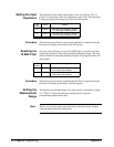

Procedure 1. Route the input signal to the attenuators.
A. To set the measurement range, the input signal must be routed to
the attenuators. This is done by setting bit 10
(channel 1) or bit 15 (channel 2) to ’1’.
2. Set the required attenuation.
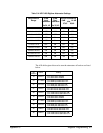
A. From Table C-1 and with the bit positions known, set the bits for
the required attenuation (measurement range) using the procedure
for reading and writing to the shift register.
3. Copy the shift register bits to the shift register latch.
A. Write a value of 4 to the A/D parallel strobe register
(base +0B
16
) to copy the shift register bits to the shift register latch.
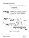
Using the Packed
Reading Format
When the measurement range is set using registers, the reading resolution
used to convert the readings to voltages is unknown to the processor. As a
result, the packed data format should be used, and the readings converted by
the user as described in Chapter 3 - "Understanding the Digitizer".
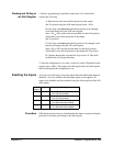
Arming and Triggering
This section contains the procedures used to configure the digitizer’s arm
and triggering (timebase) hardware.
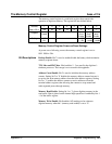
Checking the Idle
State
Except as noted, configuring the arming and triggering hardware occurs
when the digitizer is in the idle state. The register used to check the idle
state is listed below.
• Arm status register
base + 43
16
Procedure 1. Determine if the digitizer is in the idle state by checking bit 1 of the arm
status register (base + 43
16
).
If bit 1 is set to ’0’, the digitizer is in the idle state and can be configured.
If bit 1 is set to ’1’, the digitizer is in the initiated state and should not be
configured.
372 Register Programming Appendix C