


The Memory Control Registers
The following memory control registers are used to initialize digitizer
memory.
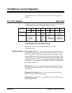
The Traffic Register base +02
16
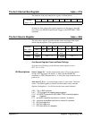
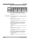
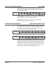
The traffic register is a read/write register that selects data and clock sources
for the high-speed data bus. The bits are defined as follows.
Address 7 6 5 4 3 2 1 0
base + 02
16
128
64 32 16 8 4 2 1
Purpose
Data Register Mode not used Read
Data
High-Speed Clock
Source
High-Speed Data
Source
Setting
0 0 - invalid
0 1 - channel 1
1 0 - channel 2
1 1 - alternate
channels
0 - data
not ready
1 - data
ready
0 0 - pulse register
0 1 - A/D
1 0 - data register
1 1 - Local bus
0 0 - A/D
0 1 - data register
1 0 - not used
1 1 - memory data
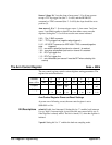
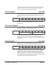
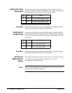
Traffic Register Power-on/Reset Settings
At power-on or following a reset, the traffic register is set to
1100 0100 or C4
16
.
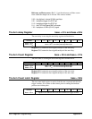
Bit Descriptions Data Register Mode. Bits 7 - 6 specify how data will be presented when
read by the data register, and how it will be written into memory as written
by the data register. Writing data to only one channel’s memory is not
recommended since invalid data is placed in the unselected channel. When
’alternate channels’ is selected, the two channels alternate, beginning with
the channel previously selected. For example, alternate channels beginning
with channel 2 can be achieved by setting the Data Register Mode field to 1
0, and then setting it to 1 1.
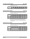
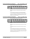
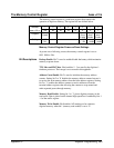
Read Data. Bit 4 is set to 1 when data can be read from digitizer memory.
See "Segmented Reading Transfers" in Chapter 3 for information on how
the bit is used.
High-Speed Clock Source. Bits 3 - 2 set the source which clocks data
transfers over the internal high-speed bus.
High-Speed Bus Source. Bits 1 - 0 select the data source which drives the
internal high-speed bus.
Appendix C Register Programming 363