


Configuring the Digitizer Input
This program demonstrates the commands used to configure the digitizer’s
input section. The program sets up the digitizer to take 10 readings on the
1V range of the digitizer’s single ended input port. This includes:
• enabling/disabling the input ports
• setting the input impedance
• switching the 10 MHz filter into the signal path.
• setting the signal range
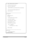
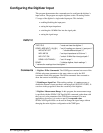
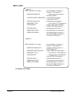
INPUT.C
*RST;*CLS /* reset and clear the digitizer */
CONF1:ARR:VOLT (10),(@1) /* set 10 readings on channel 1, input port 1 */
INP3:STAT OFF /* disable differential port 3 */
INP1:IMP 50 /* set input impedance to 50 ohms */
INP1:FILT ON /* switch 10 MHz filter into signal path */
SENS1:VOLT:RANG 1 /* set 1V range */
READ? /* initialize digitizer, fetch readings */
/* retrieve the readings from the digitizer */
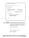
Comments 1. Digitizer INPut Commands. The CONFigure command sets most of the
(INPut) subsystem parameters to the same values as set by the INP
commands listed in the program. The INPut commands were executed to
show the context in which they are used.
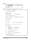
2. Disabling an Input Port. When taking readings, it is not necessary to
disable the channel’s input port that is not being used (INP3:STAT OFF). It
was done in this program to show the versatility of the digitizer.
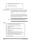
3. Digitizer Measurement Range. In this program, the measurement range
is specified with the SENSe:VOLTage:RANGe command, rather than with
the expected value parameter of the CONFigure command. For most
applications, however, it is easier to specify an expected value.
SENSe:VOLTage:RANGe can be used to change the signal range without
changing the entire digitizer configuration with CONFigure.
50 Usin
g
the Di
g
itizer Chapter 2