


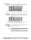
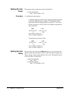

Setting the Input
Impedance
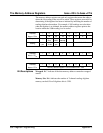
The impedance of the single-ended inputs can be set to 50Ω or 75Ω. At
power-on or following a reset, the impedance is set to 50
Ω. The impedance
is changed using the following bits of the A/D shift register.
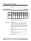
Bit
Position
Name Setting
6 TERM75 1
0 - Ch1 50
Ω input imedance selected
1 - Ch1 75
Ω input impedance select
11 TERM75 2
0 - Ch2 50
Ω input imedance selected
1 - Ch2 75
Ω input impedance select
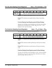
Procedure
With the bit position known, set the input impedance as required using the
procedure for reading and writing to the shift register.
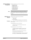
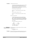
Enabling the
10 MHz Filter
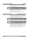
At power-on or following a reset, the 10 MHz filter is switched out of the
signal path (disabled) of the single-ended and differential inputs. The filter
can be switched into the path (enabled) using the following bits of the A/D
shift register.
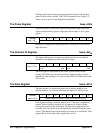
Bit
Position
Name Setting
9 FILTER1 0 - Ch1 10 MHz filter disabled
1 - Ch1 10 MHz filter enabled
14 FILTER 2 0 - Ch2 10 MHz filter disabled
1 - Ch2 10 MHz filter enabled
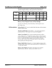
Procedure
With the bit position known, disable/enable the filter as required using the
procedure for reading and writing to the shift register.
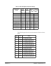
Setting the
Measurement
Range
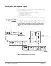
The digitizer measurement range is set using a series of attenuators (Figure
3-3). Table C-1 shows the attenuator settings used to select the
corresponding measurement range.
Note There is a 3 ms relay settling time following each range change. Samples
cannot be taken during the settling time.
370 Register Programming Appendix C