


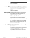

Enabling the Synchronization Signal
In order for the trigger or clock synchronization signals to be routed to the
"Ext 1" BNC port or to an ECLTRG or TTLTRG trigger line, the routing
must be enabled. This is done with the commands:
OUTPut:EXTernal[1][:STATe] <
mode
>
OUTPut:ECLTrg<
n
>[:STATe] <
mode
>
OUTPut:TTLTrg<
n
>[:STATe] <
mode
>
For each command, the <mode > settings are:
ON - enables the port or trigger line to route the signal.
OFF - disables the port or trigger line from routing the signal.
Note The ECLTRG trigger lines are independent with regard to the
synchronization signal supplied by FEED. This means that trigger lines
ECLT0 and ECLT1 (when enabled) can carry different synchronization
pulses.
The Analog-to-Digital Converter
Each channel on the HP E1429 digitizer has a 12-bit, 20 MSample/second
analog-to-digital (A/D) converter. A paper describing the A/D converter,
which was developed by Hewlett-Packard Laboratories, is available from
the following:
Jewett, R., et al., "A 12b 20MS/s Ripple-through ADC", ISSCC DIGEST
OF TECHNICAL PAPERS, pp. 34-35, Feb. 1992.
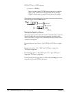
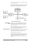
Data Flow, Storage, and Conversions
This section of the chapter covers the data flow from the A/D to digitizer
memory and to the VME (VXI data transfer) bus. A block diagram of the
data flow is shown in Figure 3-7.
Digitizer Data Flow The HP E1429 digitizer takes readings (samples) on both channels
simultaneously, even if an input signal is applied to only one channel. Each
12-bit reading is combined into a single 24-bit number which is sent to the
data processor. The processor converts the readings from ECL levels to
TTL levels.
Readings are stored and retrieved from memory as single 24-bit numbers
(see "How Readings are Stored"). Each 12-bit reading sent to the VME
(VXI data transfer) bus directly from the A/D or from memory is expanded
Chapter 3 Understandin
g
the HP E1429 Di
g
itizer 129