


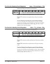

Reading and Writing to
the Shift Register
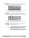
1. Define a programming loop which counts from 55 to 0 and which
contains the following.
A. Read and save the current shift register bit at the output
(bit 55) position using the A/D status register (base + 03
16
).
B. If the loop count does not equal the bit position to be changed,
write back the bit using the A/D serial register
(base + 05
16
). This restores the bit and shifts it to the bit 0 position,
which shifts a new shift register bit to the output
(bit 55) position.
C. If the loop count does equal the bit position to be changed, write
the new bit setting using the A/D serial register
(base + 05
16
). This sets the bit and shifts it to the bit 0 position,
which shifts a new shift register bit to the output (bit 55) position.
D. Continue through the loop until the loop count is 0. This shifts
each bit back to its original position.
2. After the configuration is set, write a value of 4 to the A/D parallel strobe
register (base + 0B
16
). This copies each shift register bit to the shift register
latch at which point the configuration is set.
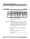
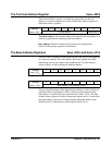
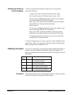
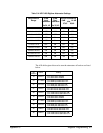
Enabling the Inputs At power-on or following a reset, the single-ended and differential inputs of
channels 1 and 2 are enabled such that input signals can be applied. An
input can be disabled (and later enabled) using the following bits of the A/D
shift register.
Bit
Position
Name Setting
7 SINGEND1 0 - Ch1 S/E input disabled
1 - Ch1 S/E input enabled
12 SINGEND2 0 - Ch2 S/E input disabled
1 - Ch2 S/E input enabled
36 CH1INPT 0 - Ch1 differential input enabled
1 - Ch1 differential input disabled
44 CH2INPT 0 - Ch1 differential input enabled
1 - Ch1 differential input disabled
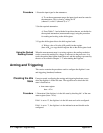
Procedure
With the bit positions known, disable/enable the inputs as required using the
procedure for reading and writing to the shift register.
Appendix C Register Programming 369