


Single Digitizer In a single digitizer configuration, the digitizer is usually the data generator
and a device such as the HP E1488 memory card is the consumer. With this
configuration, the programming sequence is:
1. Use the CONFigure command and the low-level digitizer commands
to configure the digitizer for the required measurements.
2. Use the VINStrument subsystem to reset the digitizer’s Local bus
chip, to set the Local bus transfer mode (generate), and to set the
data source (post measurement or real time transfer).
VINStrument:CONFigure:LBUS:RESet
VINStrument:CONFigure:LBUS:MODE <mode>
VINStrument:CONFigure:LBUS:FEED <source >
3. Reset the consumer’s (i.e. memory card’s) Local bus chip and
configure the consumer to receive data.
4. Activate (initiate) the consumer.
5. Use INITiate:IMMediate to activate the digitizer and start reading
transfers.
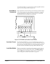
Multiple Digitizers and
Serial Transfers
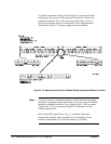
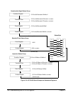
In a configuration with two or more digitizers transferring data serially, the
leftmost digitizer is set to the generate mode and the succeeding digitizer(s)
is set to either the append mode or the insert mode. A device such as the
HP E1488 memory card is usually the consumer.
In a serial transfer, each digitizer transfers data from its memory or directly
from its A/D in sequence. For example, serial transfers from digitizers D
1
-
D
3
where D
1
is in generator mode and D
2
and D
3
are in append mode
would appear as:
EOF EOB D
3
D
3
D
3
EOB D
2
D
2
D
2
EOB D
1
D
1
D
1
-----> consumer
When D
1
is in generator mode and D
2
and D
3
are in insert mode the
transfer sequence would appear as:
EOF EOB D
1
D
1
D
1
EOB D
2
D
2
D
2
EOB D
3
D
3
D
3
-----> consumer
In these sequences, EOF is the end-of-frame flag, EOB is the end-of-block
flag, and D
n
is either a two byte (one channel) or four byte (two channel)
reading. The procedure for a serial transfer is:
160 Understanding the HP E1429 Digitizer Chapter 3