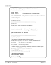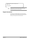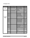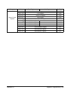
Each program uses a combination of SCPI commands and register
reads/writes. In most cases SCPI commands set the initial digitizer
configuration. Register reads/writes are used to modify the configuration,
re-initialize the digitizer, and retrieve readings.
Reading and
Writing to the
Registers
The examples in this appendix are based on the system configuration listed
previously. With this configuration, the digitizer’s A24 registers are read,
and written to, using the HP E1406 Command Module’s
DIAGnostic:PEEK?, DIAGnostic:POKE, and
DIAGnostic:UPLoad:SADDress? commands:
DIAGnostic:PEEK? <
address
>, <
width
>
DIAGnostic:POKE <
address
>, <
width
>, <
data
>
DIAGnostic:UPLoad:SADDress? <
address
>, <
byte_count
>
<address > - the address (A24 base address + register offset) of the register.
<width > - the number of bits read (DIAG:PEEK?), or the number of data
bits written to the register (DIAG:POKE). Unless otherwise noted,
register reads and writes are 8-bits.
<data >- the integer data written to the register.
<byte_count >- the number of reading bytes uploaded (read) from digitizer
memory. Since each reading is two bytes, byte_count is equal to 2 times the
number of readings to upload. In the example program at the end of this
appendix, DIAGnostic:UPLoad:SADDress? is used to retrieve all the
readings from memory once the digitizer has been re-initiated.
Note With an embedded controller, the Standard Instrument Control Library
(SICL), and the programming procedures found in this appendix, higher
throughput rates can be achieved than the rates available with the system
configuration listed. To use these procedures, note the A24 address mapping
of the embedded controller, and replace DIAG:PEEK?, DIAG:POKE, and
DIAG:UPL:SADD? with the appropriate SICL reads and writes.
342 Register Programming Appendix C


