


Level Arming
This program demonstrates:
• how to set the arm source such that the digitizer is armed when the
input signal enters a specified voltage range (window) from a level
outside the range.
• how to set the arm slope such that an arm occurs when the input
signal enters the arm window from either a positive-going or
negative-going direction.
• how to set the voltage levels which define the arm window.
For this example, the arm signal should be applied to the HI input of port 3,
with the LO input of port 3 grounded.
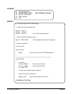
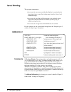
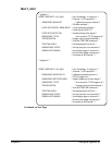
ARMLEVEL.C
*RST;*CLS /* reset and clear the digitizer */
CONF1:ARR:VOLT (10),10,(@3) /* set 10 readings on Diff port 3 */
ARM:SOUR1 INT1 /* set arm source 1 to level arming */
ARM:SOUR2 HOLD /* disable arm source 2 */
ARM:SLOP1 EITH /* arm when signal enters window from */
/* either direction */
ARM:LEV1:POS 4 /* set arm window lower boundary */
ARM:LEV1:NEG 6 /* set arm window upper boundary */
ARM:COUN 2 /* set two measurement bursts */
INIT /* put digitizer in wait-for-arm state */
FETCH? /* retrieve readings after arms occur */
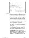
Comments 1. The Arm Window. The arming window set by this program is +4V to
+6V on the digitizer’s 10V range. The upper boundary of the window (6V)
is set with the ARM:LEVel1:NEGative command. This means when a
NEGative-going input signal reaches 6V, the digitizer is armed. Similarly,
the lower boundary (4V) of the window is set with the
ARM:LEVel1:POSitive command. Thus, when a POSitive-going input
signal reaches 4V, the digitizer is armed. Because the NEGative-going level
is greater than the POSitive-going level, the digitizer is armed each time (up
to the arm count) the signal enters the window.
2. Additional Information. Level arming is covered in detail in Chapter 3,
in the section "Arming and Triggering".
52 Usin
g
the Di
g
itizer Chapter 2