


Procedure 1. Determine the reference period.
A. The reference from which the arm delay is derived is set with bit
0 of the arm control register. The setting of bit 0 (to ’0’ or ’1’)
depends on the reference clock and the amount of delay required.
Determine the reference from which the delay is derived and set bit
0 accordingly. Retain the settings of bits 7 - 1.
If delay / reference clock period ≤ 65,534
bit 0 is set to ’1’ and the maximum delay is 65,534 * reference
period
If delay / reference clock period > 65,534
bit 0 is set to ’0’ and the maximum delay is 655,350 * reference
period
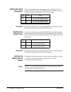
2. Load the arm delay registers.
A. Write the decimal equivalent of the most significant byte to
register 51. Write the decimal equivalent of the least significant
byte + 1 to register 53. The additional count (1) is required because
there is always a one reference cycle delay from when the digitizer
is armed to when it enters the wait-for-trigger state (i.e. is ready to
begin sampling).
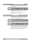
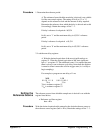
For example, to program an arm delay of 1 ms:
MSB LSB
0 1 0 0 1 1 1 0 0 0 1 0 0 0 0 1
78
10
33
10
78
10
is written to register 51
33
10
is written to register 53
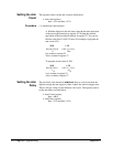
Setting the
Reference Source
The reference source from which the sample rate is derived is set with the
register listed below.
• Reference oscillator register
base +4F
16
Procedure Write the decimal equivalent bit pattern for the desired reference source to
the reference source register (base + 4F
16
). Retain the settings of bits 7 - 3.
Appendix C Register Programming 375