


STATus
The STATus subsystem controls the SCPI-defined Operation and Questionable
Signal status registers. Each is comprised of a condition register, an event register,
an enable mask, and negative and positive transition filters.
Each status register works as follows: when a condition occurs, the appropriate bit
in the condition register is set or cleared. If the the corresponding transition filter is
enabled for that bit, the same bit is set in the associated event register. The contents
of the event register and the enable mask are logically ANDed bit-for-bit; if any bit
of the result is set, the summary bit for that register is set in the status byte. The
status byte summary bit for the Operation status register is bit 7; for the
Questionable Signal status register, bit 3.
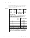
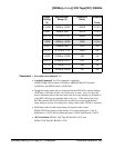
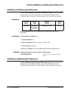
Operation Status Register
Only bits 0 (CALibrating), 6 (Waiting for ARM), 8 (BUSY), and 9 (READy) are
defined for the HP E1429. All other bits are always zero.
Bit 0 - CALibrating: Set (1) during the execution of the CALibration:ZERO,
CALibration:GAIN, or CALibration:DELay command. Cleared (0) otherwise.
Bit 6 - Waiting for ARM: Set (1) when waiting for a start arm. Cleared (0)
when a start arm is accepted or when measurement is aborted.
Bit 8 - BUSY: Set (1) by the INITiate:IMMediate,
VINStrument:CONFigure:VME:MEMory:INITiate, or
VINStrument:CONFigure:LBUS:MEMory:INITiate command. Cleared (0)
when the measurement is complete or is aborted, returning the digitizer to the
idle state.
Bit 9 - READy: Set(1) when the digitizer memory segment is ready for data
storage. Cleared (0) while the digitizer is partitioning the next memory segment.
STATus Subsystem Command Reference 265