


Configuring the Digitizer Input
This section contains the procedures used to configure the digitizer’s input
section. The configuration includes:
• Enabling the Single Ended and Differential Inputs
• Setting the input impedance
• Enabling the 10 MHz filter
• Setting the measurement range
The digitizer must be in the idle state when configuring the input section.
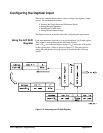
Using the A/D Shift
Register
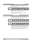
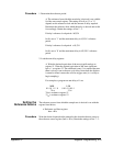
Each input parameter listed above is set by the digitizer’s A/D shift register.
This register is accessed through the A/D status register
(base + 03
16
), the A/D serial register (base + 05
16
), and by the A/D parallel
strobe register (base + 0B
16
) as shown in Figure C-2. The procedure for
setting the configuration using the register is described in the following
section.
Figure C-2. Accessing the A/D Shift Register
368 Register Programming Appendix C