


VME Bus Data Transfers
Another method of transferring readings to the VME (VXI data transfer)
bus is with the digitizer’s VINStrument (Virtual INStrument) subsystem
and accessing the digitizer’s data register. This method, which combines
message-based (SCPI) programming and reading the data register directly,
is faster than the previous methods (READ?, FETCh?,
DIAGNostic:UPLoad:ADDRess?) in that readings can be retrieved from
the A/D converter or from memory in the A/D’s packed data format.
There are two modes of VME data transfers: real-time and post
measurement. In a real-time data transfer, reading the digitizer’s data
register triggers a measurement and returns the A/D reading to the VME bus
in the same measurement cycle. In a post measurement data transfer,
reading the register transfers a A/D reading from digitizer memory to the
VME bus.
How to select the transfer mode is covered in the section "Setting the VME
bus Transfer Mode". Examples of VME bus data transfers are listed in
Chapter 2 - "Using the Digitizer".
Locating the Data
Register
Access to the digitizer’s data register is through its address which is mapped
into A24 address space. At power-on, the system resource manager reads
the digitizer’s device type register (in A16 address space) to determine the
amount of A24 memory the digitizer needs (which is 4096 bytes). The
resource manager allocates a block of A24 memory for the digitizer and
writes the A24 base (starting) address into the digitizer’s offset register
(also in A16 space).
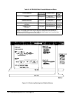
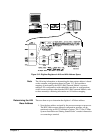
Figure 3-12 is an example of how the digitizer registers are mapped into
A16 and A24 address space. Appendix C contains additional register
programming information.
146 Understandin
g
the HP E1429 Di
g
itizer Chapter 3