


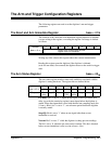
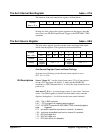
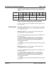

Last TRG*: Bit 4 is set to ’0’ when the last programmed arm count is
reached (base + 55
16
and base + 57
16
). The bit is set to ’1’ when the burst of
readings associated with the arm are complete.
Begin samp: Bit 3 is set to ’0’ with the first reading in each arm burst and
is set to ’1’ after the last reading in each arm burst.
Delayed: Bit 2 is set to ’1’ after the programmed arm delay (base + 51
16
and base + 53
16
) has elapsed.
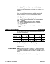
Initiated: Bit 1 is set to ’1’ when the digitizer is initiated and can accept an
arm trigger. This bit is monitored when taking multiple bursts of pre- and
post-arm readings and transferring the readings over the VME bus. Multiple
bursts of pre- and post-arm readings segment memory (Figure 3-13). There
is a period (partition window) between each segment that is used by the
processor to set up the next segment. When bit 1 is set to ’1’, the next
segment is ready for data storage and transfer. See "VMEbus Data
Transfers" in Chapter 3 for more information.
Initialized: Bit 0 is set to ’1’ when the digitizer is initialized and is ready to
accept an initiate pulse.
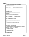
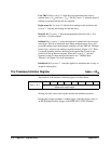
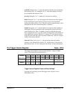
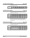
The Timebase Initiation Register base + 45
16
The function of the timebase initiation register is defined below.
Address 76543210
base + 45
16
register write: initiates the timebase processor
register read: sample trigger
Writing any 8-bit value to the register initiates the timebase processor.
Reading this register generates a sample trigger when the trigger source is
an HP-IB Group Execute Trigger or the IEEE-488.2 *TRG command.
354 Register Programming Appendix C