


1. Use the CONFigure command and the low-level digitizer commands
to configure the digitizers for the required measurements.
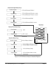
2. Use the VINStrument subsystem to reset the leftmost digitizer’s
Local bus chip, to set the Local bus transfer mode to generate,
and to set the data source (post measurement or real time
transfer).
Use the VINStrument subsystem to reset the inner digitizer’s
Local bus chip, to set the Local bus transfer mode to append or
insert, and to set the data source (post measurement or real time
transfer).
VINStrument:CONFigure:LBUS:RESet
VINStrument:CONFigure:LBUS:MODE <mode>
VINStrument:CONFigure:LBUS:FEED <source >
Note that you must reset the Local bus chip of each appender or
inserter digitizer each time the generator digitizer’s Local bus mode
or data source is changed.
3. Reset the consumer’s (i.e. memory card’s) Local bus chip and
configure the consumer to receive data.
4. Activate (initiate) the consumer.
5. If the digitizer(s) is in the append mode, use INITiate:IMMediate to
activate the appender digitizer first. Then use INITiate:IMMediate to
activate the generator digitizer.
6. If the digitizer(s) is in the insert mode, use INITiate:IMMediate to
activate the generator digitizer first. Then use INITiate:IMMediate to
activate the inserter digitizer.
Digitizer
Configuration
Restrictions
The HP E1429B digitizer can be configured for measurements as required
with the following exceptions:
• If the Local bus data source is the digitizer A/D (real time transfers),
only post-arm readings are allowed. This includes multiple arms
(bursts).
• When the Local bus mode is set to a mode other than OFF or
pipeline, the VME bus transfer mode must be disabled. This is done
with the command:
VINStrument[:CONFigure]:VME[:MODE] OFF
Chapter 3 Understanding the HP E1429 Digitizer 161