


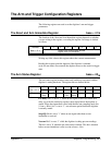
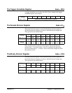
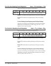

Source 1 slope: Bit 3 sets the slope of arm source 1. For all arm sources
except a TTLTrg trigger line (bits 2 - 0 =001) and the HP-IB GET
command or *TRG command (bits 2 - 0 =010), the slope should be set to
positive (0).
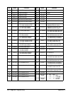
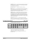
Arm source 1: Bits 2 - 0 set arm trigger source 1. Arm source 2 and arm
source 1 are ORed together so that an arm from either source arms the
digitizer. Setting bits 2 - 0 as follows sets the arm source indicated.
0 0 0 - "Ext 1" BNC connector.
0 0 1* - TTLTrg trigger line (negative-edge triggered)
0 1 0* - HP-IB GET command or IEEE-488.2 *TRG command(negative
edge triggered)
0 1 1 - arm when a specified input level on channel 1 is reached
1 0 0 - arm when a specified input level on channel 2 is reached
1 0 1 - ECLTrg0 trigger line
1 1 0 - ECLTrg1 trigger line
1 1 1 - arm immediate (arm source 2 must be OFF when selecting this
source)
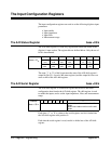
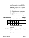
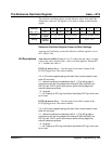
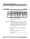
The Arm Control Register base + 4B
16
The arm control register controls various digitizer arming parameters. The
register bits are defined below.
Address 7 6 5 4 3 2 1 0
base + 4B
16
128
64 32 16 8 4 2 1
Purpose
not used enintr0
2 speed reclk/
10
pre-trig thold triginf delay
ref
Setting
--- 0 - off
1 - on
0 - off
1 - on
0 - off
1 - on
0 - off
1 - on
0 - off
1 - on
0 - off
1 - on
0 - off
1 - on
Arm Control Register Power-on/Reset Settings
At power-on or following a reset, the arm control register is set to
0000 0001 or 01
16
.
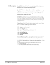
Bit Descriptions enintr0: Enable local interrupt 0. Setting bit 6 to ’1’ enables local interrupt
0 to go ’high’ if an arm trigger is received while arm source hold is set, or
if the digitizer is already armed. The bit is cleared (’0’) when the digitizer is
initiated.
2 speed: Setting bit 5 to ’1’ enables the dual rate sampling mode.
356 Register Programming Appendix C