


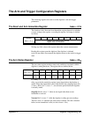
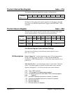

reclk/10: Setting bit 4 to ’1’ causes the reference divider to be reclocked by
the reference clock / 10. Setting bit 4 to ’0’ causes the reference divider to
be reclocked by the reference clock.
pre-trig: Setting bit 3 to ’1’ enables pre- and post-arm readings.
thold: Setting bit 2 to ’1’ sets arm trigger hold which prevents the digitizer
from accepting arm signals from any source except an arm immediate
(writing any value to base + 41
16
). This bit is used to suspend arming while
changing the arm source when the digitizer is initiated.
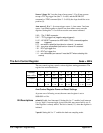
triginf: Setting bit 1 to ’1’ sets the digitizer to accept an infinite number of
arm triggers. The bit overrides the arm count registers, however; the arm
count remains active. Thus, if a number of arms less than the arm count
have occurred when bit 1 is set, the counter will keep track of the number of
arms which have occurred. When bit 1 is cleared (’0’), the digitizer returns
to the idle state if the arm count was reached. Otherwise, arms are accepted
until the arm count is reached.
delay ref: When bit 0 is set to ’1’ , the arm delay is derived from the
reference clock. When bit 0 is cleared (’0’), the arm delay is derived from
the reference clock / 10. See "Setting the Arm Delay" for more information.
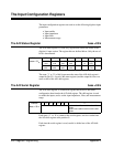
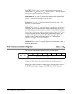
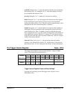
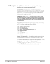
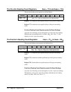
The Trigger Source Register base + 4D
16
The trigger source register is used to set the digitizer’s trigger (sample)
source. The register bits are defined below.
Address 7 6 5 4 3 2 1 0
base + 4D
16
128
64 32 16 8 4 2 1
Purpose
Sample/
Hold
Sample
Infinite
Sample
Once
Trigger Source Internal TTL
Sources
Setting
0 - OFF
1 - ON
0 - OFF
1 - ON
0 - OFF
1 - ON
0 0 0 - 1 1 1 0 0 - 1 1
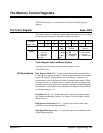
Trigger Source Register Power-on/Reset Settings
At power-on or following a reset, the trigger source register is set to
0010 0000 or 20
16
.
Appendix C Register Programming 357