


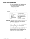
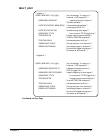
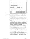

/* digitizer commands */
INIT /* put digitizer 1 in wait-for-arm state */
INIT /* put digitizer2 in wait-for-arm state */
/* Command Module commands */
OUTP:TTLT0:STAT ON /* enable line TTLT0 */
"Press Enter (return) to arm the digitizers"
OUTP:TTLT0:IMM /* apply a pulse to TTLT0 */
/* digitizer commands */
FETC1? /* retrieve readings from digitizer1, channel 1 */
FETC2? /* retrieve readings from digitizer1, channel 2 */
FETC1? /* retrieve readings from digitizer2, channel 1 */
FETC2? /* retrieve readings from digitizer2, channel 2 */
Comments 1. Synchronizing Digitizers. By routing (OUTPut) the reference clock
from one digitizer to all digitizers in the system, the sample rate is derived
from the same reference. Digitizer samples can then be taken at precise
intervals of each other.
2. Input Channels. In this program, samples are taken on the single ended
and differential inputs of two digitizers, for a total of four channels. When
sampling, either the channel’s single ended input or the differential inputs
can be used. You cannot use both sets of inputs simultaneously on a single
channel.
3. CONFiguring Channels Independently. In this program, the digitizers’
single ended input ports (channel 1) and differential input ports (channel 2)
are set to two different signal ranges. This was done using
SENSe:FUNCtion to select the port and SENSe:VOLTage[:DC]:RANGe to
set the range. CONFigure was not used since executing
CONF2:ARR:VOLT (10),5,(@3) would not only set the range on channel
2, but would also change the settings made following the first CONFigure
(CONF1) command.
4. Routing/Sourcing Signals. If a digitizer trigger port (e.g. "Ext 1", "Ext
2") or a VXI backplane trigger line (ECLTrg<n >, TTLTrg<n >) is the
source of a reference signal, arm signal or trigger signal, then that port or
line cannot be used to route (OUTPut) a synchronization signal.
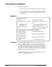
5. Retrieving Readings. When readings are retrieved from digitizer
memory using the FETCh? command, each channel’s readings must be
retrieved separately. That is, channel 1’s readings must be fetched and then
channel 2’s must be fetched, or vice versa. However, VME bus data
transfers (retrievals) allow both channels’ readings to be retrieved
simultaneously. The "VME Bus Data Transfers" examples in this chapter
show how this is done.
58 Usin
g
the Di
g
itizer Chapter 2